EC590
Function code table
-
153
-
-
154
-
4. Add a reactor or magnetic ring to the output side of the AC drive.
The temperature of the motor rises
When the motor is used for variable speed operation, if the motor is a synchronous
ventilation type induction motor, it will have a cooling effect at low speeds. Poor,
so overheating may occur. In addition, the waveform output by the AC drive con-
tains high-order harmonics, so copper loss and iron loss are increased.
Check the data for the load status and operating range for reference, and add the
following countermeasures when necessary:
1. The motor is changed to an independent power supply ventilation type or the
first-level capacity specification is improved.
2. The motor matching is changed to a special motor for AC drive.
3. Limit the operating range and avoid low-speed belt operation.
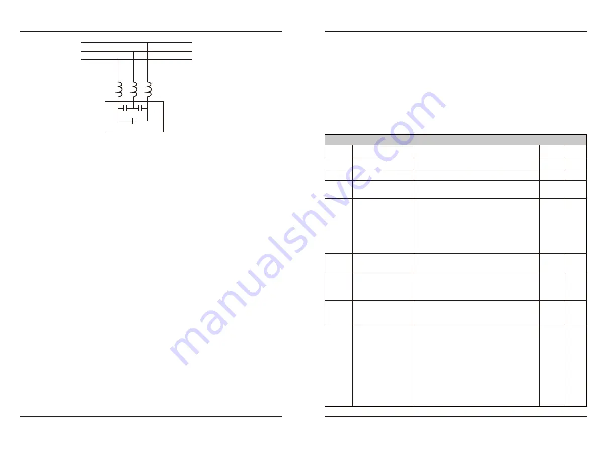
Series reactor
Phase advance capacitor
8. Appendix
8.1 Appendix I: F
unctionalcodetable
When FP-00 is set to a non-zero value, the parameter protection password is set. In
the function parameter mode and user change parameter mode, the parameter menu can only
be entered after correctly entering the password. Set FP-00 to 0 to cancel the password.
The parameter menu in user-defined parameter mode is not password protected.
Group F and group A are basic function parameters, and group u is monitoring
function parameters.
☆ : It is possible to modify the parameter with the AC drive in the Stop and in the
Run status.
★ : It is not possible to modify the parameter with the AC drive in the Run status.
● : The parameter is the actual measured value and cannot be modified.
*: The parameter is a factory parameter and can be set only by the manufacturer.
F0
Standard Parameter group
Change
Function
Code
F0
-
00
AC drive G/P
selection
Setting Range
1: G (constant torque load)
2: P (fan and pump)
F0
-
02
F0
-
03
F0
-
04
F0
-
06
F0
-
05
Main frequency
reference setting
channel selection
Range of auxiliary
frequency reference
for main and
auxiliary calculation
Running command
selection
Auxiliary frequency
reference setting
channel selection
Base value of
range of auxiliary
frequency reference
for main and
auxiliary calculation
☆
★
★
☆
☆
0: Operating panel (
LED off)
1: Terminal(
LED
on
)
2: Serial communication(
LED
flashing
)
0: Digital setting (revised value is
n
ot
cleared after power off)
1: Digital setting (revised value is cleared
after power off)
2: AI1 3: AI2
4:
Keyboard
potentiometer
5: Pulse setting (
S
5)
6: Multi-reference 7: Simple PLC
8: PID reference
9: Communication setting
Same as F0-03 (Main frequency reference
setting channel selection)
0% to 150%
0: Relative to maximum frequency
1: Relative to main frequency reference
Default
1
0
1
0
0
100%
Final Frequency
reference setting
selection
F0
-
07
☆
Ones: Frequency reference selection
0: Main frequency reference
1: Main and auxiliary calculation (based on
tens position)
2: Switchover between main and auxiliary
3: Switchover between main and "main &
auxiliary calculation"
4: Switchover between auxiliary and "main &
auxiliary calculation"
5.Any non-0 value of the main and auxiliary
channel is valid, main channel first.
Tens: main and auxiliary calculation formula
0: Main + auxiliary 1: Main - auxiliary
2: Max. (main, auxiliary)
3: Min. (main, auxiliary)
00
Parameter Name
★
F0
-
01
Motor 1 control mode 0: SVC
2: V/F
2
★
EC590
Faults and solutions


