Setup Procedure
057-281 ISSUE: 1
Page 22 of 58
4.2.2 LOW OUTPUT VOLTAGE AFTER FIRST START
If the generator output voltage is not reaching the configured
Set Point
, check that the voltmeter
reading is consistent with the
Feedback Voltage
on the Commissioning Screen display. If there is a
difference in the reading, this indicates a mistake in the alternator sensing wires or configuration.
For example,
if a 440 V (phase to phase) alternator is connected ‘half phase’, this results in 220 V
(phase to phase) being connected to the AVR
L
and
N
terminals. The
Feedback Voltage
shows 220 V,
the voltage measured by the AVR. The AVR
Set Point
must be configured to match the sensing voltage
as the AVR works to adjust the excitation to achieve and maintain the sensed voltage to match the
configured set point.
If the voltmeter and SCADA display are
consistent, but not reaching the full
feedback voltage, then check if an
Integral Limit
warning is active. The
Integral Limit
warning is viewed in either
the
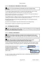
‘Output Duty Cycle’ box on the
Diagnostic Screen, or
in the ‘Status’ box on the Commissioning Screen. This indicates that the
Maximum Duty Cycle
is set too low in the configuration. Stop the set and increase the value to 100 %,
then repeat the test.
4.3 AFTER A SUCCESSFUL START
NOTE: Proceed below only when the generating set runs without the AVR tripping and
when the feedback voltage reaches the set point and remains stable.
NOTE: For further details of module configuration, refer to DSE Publication: 057-271
DSEA108 Configuration Suite PC Software Manual.
4.3.1 OFF LOAD DUTY CYCLE SETTING
With the set running
off load
, take note
of the
Output Duty Cycle
being displayed
on the Diagnostic or Commissioning
Screen in SCADA.
Stop the set and configure the
Off Load
Duty Cycle
to this value, i.e.
Off Load
Duty Cycle
is the normal ‘off load’
operating point.
Integral Limit
warning


