Setup Procedure
057-281 ISSUE: 1
Page 24 of 58
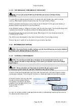
4.3.2.3
VOLTAGE SET POINT STEP
The
Voltage Set Point Step
feature allows the
configured stability settings to be tested,
without the use of a load bank. The voltage
Set
Point
is increased and decreased by a pre-
defined percentage, at the set interval for a set
number of cycles. For commissioning
the default values of 10 intervals, voltage steps of 10 % and interval delay of 5 seconds is used.
When the
Voltage Set Point Step
is activated the AVR first increases the excitation output voltage to
increase generator output voltage. If this increase is too large, the set point is surpassed, requiring a
decrease in excitation. The inverse of this process then occurs; the AVR decreases the excitation
output voltage to decrease generator output voltage. As with the step-up, if the decrease is too large,
the set point is surpassed, requiring an increase in excitation.
The AVR’s response to these
Voltage Set Point Step
changes indicate how well the current stability
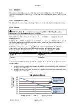
settings handle load changes, and what further adjustments may be required. Example oscilloscope
traces of the AVR’s ‘transient response’ to
Voltage Set Point Step
changes are shown below:
Too much oscillation
Good response
No change required
Response too small resulting in
With the
Proportional
and
Integral
presets set as described in the procedure above, the initial
response to the
Voltage Set Point Step
changes is likely to have been unstable. The next step to
improve this response is to increase the
Derivative
preset.
Load increase applied here.


