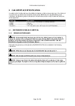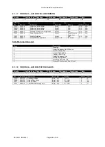
Operation
057-281 ISSUE: 1
Page 36 of 58
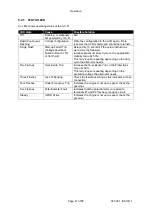
5.1.1 PRESETS
It is possible to disable the operation of the preset using DSE Configuration Suite PC Software in
conjunction with DSE815 Interface. In this instance, the value of the disabled preset is fixed by the PC
Software.
5.1.1.1
VOLTAGE SET POINT
The Setting for the alternators output voltage. Turning the preset clockwise raises the output voltage.
5.1.1.2
DROOP
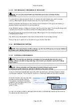
NOTE: Use of the Droop functions requires a droop CT to be fitted. See the section
entitled Setup Procedure elsewhere in this document.
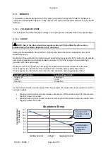
Setting for the Quadrature Droop function. Turning the preset clockwise increases the amount of
Quadrature Droop.
Quadrature Droop monitors the reactive power provided by the generator to the load and is to provide
kvar sharing (reactive load sharing) between generator or to limit kvar output when paralleling a
generator with the mains supply.
Reactive Power is the power used to supply the capacitive and inductive elements of the load.
Power supplied to a load that is more capacitive than inductive has a leading power factor.
Power supplied to a load that is more inductive than capacitive has a lagging power factor.
Lagging Power Factor
Leading Power Factor
Lagging pf
Leading pf
+kvar
-kvar
Inductive
Capacitive
As the AVR monitors the reactive power from the generator, its measurements are used to control the
excitation output:
•
Lagging reactive power (+kvars) causes a decrease in AVR excitation output to provide more
“leading” power to the load.
•
Leading reactive power (-kvars) causes an increase in AVR excitation output to provide more
“lagging” power to the load.
90
92
94
96
98
100
102
104
106
E
xc
it
atio
n
O
u
tp
u
t
(%
o
f No
min
al)
leading (-kvars) unity pf lagging (+kvars)
Quadrature Droop
Nominal AVR
Excitation output
(0 kvar)
AVR Excitation
output due to
Quadrature
Droop.


