background image

SECTION 1 GENERAL INFORMATION    

8

0855849enf 6/08

package

See product.

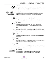
print station

The complete assembly consisting of the enclosure, electrical 
components, user interface module, and ink delivery module.

product

The material or item onto which the coder prints. Also called carton, case, 
package, 
or packaging.

product ID reader

A bar code reader that scans product information to determine which job 
file to print.

purge

The forcing of trapped air and hot ink through the jet array for a few 
seconds.

reader

See bar code reader.

registration

The location of the printed image on the package, based on whether the 
print trigger is determined by a sensor or fixed spacing setting.

reservoir

A receptacle inside the printhead that stores ink.

SC

The Model 5200 SC and 5400 SC have an ink delivery module that uses 
ink blocks instead of ink bottles.

SICK

A manufacturer of bar code readers which interface with the coder.

signal tower

An optional device consisting of a set of lamps to indicate coder status. 
Formerly called fault beacon.

SSCC

Serialized Shipping Container Code.

umbilical

The assembly including the ink line, electrical line, and vacuum line that 
connects the printhead to the enclosure.

user interface module

The keypad and display mounted to the top of the enclosure for the user to 
enter and receive information about the coder.

VPC

Vacuum Pressure Controller.

warning

A fault that generates a message on the display, but does not stop printing.

Summary of Contents for Markem-Imaje 5000 Series

Page 1: ...o p e r a t i o n g u i d e ...

Page 2: ......

Page 3: ...hts Reserved REFERENCE LIST The information on your packing slips can be written below for reference When contacting Markem Imaje please give your Model Number Serial Number and Customer Account Number Model __________________________________________________________________ Serial Number ___________________________________________________________ Customer Account Number ___________________________...

Page 4: ...iv 0855849enf 6 08 ...

Page 5: ... Programs 13 5 0 Label and Symbol Identification 14 6 0 Removal from Service 17 SECTION 2 19 Basic Operation 1 0 Basic Components 21 2 0 The Power Switch 23 2 1 Powering On the Coder 23 2 2 Powering Off the Coder 24 3 0 The User Interface Module 25 3 1 LED Indicators 26 3 2 Navigation 27 3 2 1 Menu Functions 27 3 2 2 Function Keys 28 3 2 3 ENTER and EXIT Keys 28 3 2 4 START and STOP Keys 29 3 2 5 ...

Page 6: ...e LCD Contrast 43 5 2 Setting the Registration 45 6 0 Database Management 48 SECTION 4 49 Cleaning and Care 1 0 Daily Cleaning of the Printhead 51 1 1 Purging 52 1 2 Jet Testing 53 1 3 Wiping 54 2 0 Cleanup 54 SECTION 5 55 Troubleshooting 1 0 Troubleshooting Guidelines 57 2 0 Signal Lights 57 2 1 LED Indicators on the Print Station 57 2 2 Signal Tower Lights 58 2 3 LED Indicator on the Printhead 5...

Page 7: ...Model 5200 5400 Operation Guide SECTION 1 General Information ...

Page 8: ......

Page 9: ...MARKEM Composer or CoLOS Create image design software which allow for input of variable data and multiple languages Composer or CoLOS Create job files are downloaded to the coder for printing images on your product or package The coder can be connected to a dedicated computer or networked with a host computer for connection to multiple Markem Imaje coders Operation is controlled through a user int...

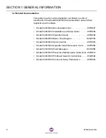
Page 10: ...on Set 0855847 Model 5200 5400 Installation and Setup Guide 0855848 Model 5200 5400 Operation Guide 0855849 Model 5200 5400 Menu Tree Diagram 10020356 Model 5200 5400 Service Guide 0855855 Model 5200 5400 Operator Quick Reference Card 0855856 Model 5200 5400 Fault Messages 10019996 Model 5200 5400 Preventive Maintenance Instructions 0840813 Model 5200 5400 Printhead Soak Kit Instructions 0840546 M...

Page 11: ...job parameters including the image data is called a job file The images for all printheads in the job file are called the label The job file must be downloaded from the computer to the coder Then the job file must be selected before printing on your product or package The Composer or CoLOS Create software manuals describe how to design name and save job files The Database Management section of the...

Page 12: ...nal injury chamber A receptacle in the ink delivery module that stores ink CimControl MARKEM proprietary software for networking multiple coders coder A machine such as the Model 5200 or 5400 that is primarily used to print codes on the customer s product Composer MARKEM proprietary software for designing images for the coder CoLOS Control MARKEM proprietary network software for data transfer remo...

Page 13: ... the ink jet array The area on the front of the printhead that ejects droplets of ink onto the customer s product jet test The process of printing a pattern used to confirm the proper operation of all jets job See job file job file A set of parameters that determines what how where and when images will print Before printing the image data must be downloaded to the coder from the host computer labe...

Page 14: ... determined by a sensor or fixed spacing setting reservoir A receptacle inside the printhead that stores ink SC The Model 5200 SC and 5400 SC have an ink delivery module that uses ink blocks instead of ink bottles SICK A manufacturer of bar code readers which interface with the coder signal tower An optional device consisting of a set of lamps to indicate coder status Formerly called fault beacon ...

Page 15: ...n personal injury 4 1 Certification The Model 5200 5400 has been designed to meet the following standards and specifications CE Marked 98 37 EC Machinery Directive 73 23 EEC Low Voltage Directive Laws for electrical equipment within certain voltage limits 89 336 EEC EMC Directive Laws relating to electrical magnetic compatibility EN 60204 1 Electrical Safety EN 61000 6 4 Generic Emission EN 61000 ...

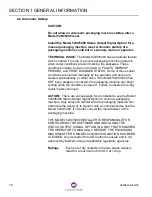
Page 16: ...has NOT been properly connected the packaging machine can begin cycling when the condition is cleared Failure to observe this may result in personal injury ACTION There are various ways for an installer to use the Model 5200 5400 Status Output Signal Option to control a packaging machine Only someone familiar with the packaging machine can determine the best way to signal it with an external devic...

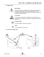
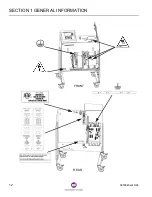
Page 17: ...r Electronic troubleshooting must be performed by personnel trained to troubleshoot electrical circuits Hot Surfaces To prevent injury from burns be careful not to touch the jet array surface or hot ink directly Wear protective eyeglasses when working with hot ink Protective Earth This label identifies a protective earth point Earth This label identifies an earth point 4 4 Location of Safety Label...

Page 18: ...SECTION 1 GENERAL INFORMATION 12 0855849enf 6 08 FRONT REAR ...

Page 19: ...aining to the installation use and repair of this coder including the use and disposal of related chemicals Operating an unserviceable incomplete or modified coder Not observing safety messages and labels Permitting an unqualified person to operate or repair this coder See Training Programs Combining or interfacing other equipment with this coder for anything other than the intended use Using supp...

Page 20: ... changes affix the appropriate voltage configuration label to the Serial I D Rating label on the rear panel of the enclosure so it covers the old voltage configuration rating Earth Label for Printheads This label is located above the I O panel and indicates the earth points for the four printheads Consult Installation Instructions This label advises the installer in both English and French to cons...

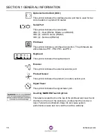
Page 21: ...mbol is located near the INK LED on the user interface module and indicates whether or not the ink supply is sufficient Start This symbol is located on the START key on the keypad and is used to start printing Stop This symbol is located on the STOP key on the keypad and is used to stop printing Enter This symbol is located on the ENTER key on the keypad and is used to open the selected menu or ac...

Page 22: ...ction The printheads are abbreviated as PH1 PH2 PH3 and PH4 Keyboard This symbol indicates the keyboard port Encoder This symbol indicates the external encoder port Product Sensor This symbol indicates the product or carton sensor port Signal Tower This symbol indicates the signal tower port Use Only MARKEM Touch Dry Ink This label is located both on the top of the printhead and near the ink chamb...

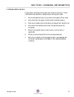
Page 23: ...off the coder 2 Disconnect the AC power cord from the electrical source 3 Disconnect cables and connections accessed from the I O door 4 Disconnect the umbilical lines from the printhead and the enclosure 5 Remove the signal tower carton sensor and encoder if applicable 6 Remove each printhead from its mounting assembly 7 Move the enclosure to the desired location and package the enclosure printhe...

Page 24: ......

Page 25: ...Model 5200 5400 Operation Guide SECTION 2 Basic Operation ...

Page 26: ......

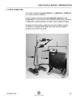
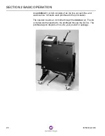
Page 27: ... The print station consists of the user interface module 4 and enclosure 5 The enclosure is the cabinet that houses the electrical components vacuum pressure controller and ink delivery module Mounted to the top of the enclosure is the user interface module consisting of a keypad and display which are used to operate program and monitor the coder 1 2 3 4 5 ...

Page 28: ...nk line vacuum line and electrical line connects each printhead to the print station The operator inserts an ink bottle through the ink door 2 The ink is melted and transported to the printhead through the ink line The printhead ejects droplets of ink onto your product or package 2 1 ...

Page 29: ...coder The green STATUS LED will blink The Version menu will appear briefly The Top Level menu will appear The status message will say Warming up or Shut Down If the status message indicates the coder is shut down the start up process can be initiated by pressing F3 Start Up A prompt will ask you to confirm that you want to start up Select YES The amber LED on the printhead will begin to blink Afte...

Page 30: ...o cool down the coder 1 To stop printing press STOP 2 From the Top Level menu press F3 Shutdown A message on the display will ask for confirmation 3 Press Fl Yes to confirm that you want to shut down Press F2 No to cancel the shutdown 4 Wait for the coder to cool and the Shutdown Done message to appear which may take three or four hours 5 Turn the power switch to the 0 position to remove power fro...

Page 31: ... 3 are used to operate program and monitor the coder Various menus will appear on the display The Top Level menu is shown below 1 2 3 25 June 2006 15 17 49 Status Machine Ready PH1 On State Printing PH2 On Ink OK Counts Batch 999 Total 53796 Press ENTER to preview image Job Chocolate Job Select Reg Main Menu Shutdown ...

Page 32: ... condition The green STATUS LED indicates whether conditions are met for printing On Online Off Power is off Blinking Warming up cooling down fast blinking or Ready slow blinking The blue INK LED indicates when the coder needs ink Off Bottle of ink is present On Add ink bottle Blinking Add ink bottle immediately The amber FAULT LED indicates when the coder needs attention Off No error or warning O...

Page 33: ...or Down Arrow will appear on the display The symbols are intended to inform the user that additional options are listed above or below When Page Up and Page Down buttons appear on the display the corresponding function key will display the previous or next portion of the menu or list The Modify button appears on the display when the selected parameter has a value that can be changed A box will ope...

Page 34: ...Function keys often open new menus 3 2 3 ENTER and EXIT Keys The ENTER key 1 is used to open the selected menu Changes that were made to the current menu will be saved when the ENTER key is pressed The EXIT key 2 is used to return to the previous menu 25 Jun 2006 15 17 49 Status Machine Ready PH1 On State Printing PH2 On Ink OK Counts Batch 999 Total 53796 Press ENTER to preview image Job Chocolat...

Page 35: ...xt 3 2 6 Select Characters Dialog Box When asked to enter text a Select Character dialog box will appear The keypad is used to select one character at a time Each character selected will be inserted at the insertion point 1 Use the arrow keys or F3 Back and F4 Forward to highlight a character When the desired character is highlighted press F1 Select Character The selected character will appear at ...

Page 36: ...pective F1 F2 F3 and F4 keys on the keypad The Esc key on the keyboard is equivalent to the EXIT key on the keypad The Enter key on the keyboard is equivalent to the ENTER key on the keypad The Backspace key on the keyboard deletes the character to the left of the insertion point and is equivalent to the Delete button on the Select Character dialog box on the display The directional arrow keys on ...

Page 37: ...o confirm the proper operation of all jets The Purge button 6 is located next to the purge symbol on the rear of the printhead It is used to force trapped air and hot ink through the jet array for a few seconds 4 2 Printhead Status The Top Level menu reports the status of each printhead The amber LED 7 on the rear of the printhead is also used to monitor the status of the printhead The LED is on w...

Page 38: ......

Page 39: ...Model 5200 5400 Operation Guide SECTION 3 Printing ...

Page 40: ......

Page 41: ... the start up process can be initiated by pressing F3 Start Up A prompt will ask you to confirm that you want to start up Select YES 3 Wait for the blinking green STATUS LED to begin to blink slowly It takes about 60 minutes for the ink delivery module and ink lines to warm up and for the coder to be ready for printing It could take longer in colder environments or if the supplied voltage is low 2...

Page 42: ...The status of the ink supply The status of each printhead Batch count and total count Instructions to preview the image or to go online The Job Select button F1 The Registration button F2 The Shutdown button F3 The Main Menu button F4 25 Jun 2006 15 17 49 Status Machine Ready PH1 On State Offline PH2 On Ink OK Counts Batch 999 Total 53796 Press ENTER to preview image Job Chocolate Job Select Reg M...

Page 43: ...function keys to change field data Press ENTER to select the job Follow the prompts To select the job press F4 Select This Job NOTE To return to the Select Job Menu press EXIT 3 If the name of the desired job is displayed press the Down Arrow key until the pointer is beside the name of the job that you want to select Press ENTER The job becomes the selected job 4 If the name of the desired job is ...

Page 44: ...on point left or right Use F2 Delete to delete the character to the left of the insertion point When the name of the desired label is displayed press ENTER 7 If the selected job has fields that can be changed by the user a menu listing the dynamic fields will open Use the arrow keys and function keys to change field data Press ENTER to select the job Follow the prompts 8 If the desired job cannot ...

Page 45: ...e directional keys can be used to better view the image Press the Up Arrow key to increase magnification Press the Down Arrow key to decrease image magnification Press the Left Arrow key to slide the image right Press the Right Arrow key to slide the image left 25 Jun 2006 15 17 49 Status Machine Ready PH1 On State Offline PH2 On Ink OK Counts Batch 999 Total 53796 Press ENTER to preview image Job...

Page 46: ... 2 3 or 4 press the appropriate function key F2 F3 or F4 6 Press EXIT to return to the Top Level menu 3 0 Production Printing Ensure that the following conditions are met The green STATUS LED is blinking slowly The blue INK LED is OFF If the LED is blinking or continuously on add a bottle of ink See Adding Ink in this section The amber FAULT LED is OFF The amber LED on the rear of the printhead is...

Page 47: ...ARKEM TouchDry ink Markem Imaje ink is specially formulated and tested for use with the Model 5200 5400 or Model 5200 5400 SC coder Failure to use Markem Imaje ink can result in machine damage and void the machine warranty NOTE Close the ink door after adding ink When the ink door is left open for an extended period of time a beep will sound When the beep becomes continuous the coder will pause un...

Page 48: ...INTING 42 0855849enf 6 08 4 2 Adding an Ink Block 1 Open the ink door 2 Remove the two ink blocks from their wrappers 3 Insert one ink block into each slot 4 Close the ink door The ink door will lock in 60 seconds ...

Page 49: ...in Menu press F4 Machine Setup If required enter a password The Machine Setup menu will appear 3 Use the Down Arrow key until the pointer is beside User Interface 25 Jun 2006 15 17 49 Status Machine Ready PH1 On State Offline PH2 On Ink OK Counts Batch 999 Total 53796 Press ENTER to preview image Job Chocolate Job Select Reg Main Menu Shutdown Access Level Level 3 Printhead 1 Settings Printhead 2 ...

Page 50: ... F1 to increase the display contrast Press F2 to decrease the display contrast The minimum value is 0 and the maximum value is 100 The default value is 70 7 When the desired contrast is set press EXIT until the Top Level menu appears Units Metric mm Language English Key Beeper Disable LCD Contrast Clock Settings 18 Sep 2006 15 37 37 Page Down 70 Modify User Interface Settings ...

Page 51: ...ont of the desired location printing too early increase the registration If the print is located behind the desired location printing too late decrease the registration When the Print Trigger is set to Sensor 1 or Sensor 2 the registration parameter appears in the Machine Setup Menu Registration is the distance before printing after the product passes by the selected sensor When the Print Trigger ...

Page 52: ...imum value is 1000mm 2 39 37 and the maximum value is 1000 39 37 The default value is 0 mm NOTE The sum of the offset and printhead registration values cannot be less than 0 25 Aug 2006 15 17 49 Status Machine Ready PH1 On State Offline PH2 On Ink OK Counts Batch 999 Total 53796 Press ENTER to preview image Job Chocolate Job Select Reg Main Menu Shutdown Reg Offset 1 mm PH Total Trigger PH Reg PH1...

Page 53: ...When the desired registration offset value is displayed press ENTER to return to the Registration Offset Menu 4 To change the PH Reg for a specific printhead press the Down Arrow until the pointer is beside the desired printhead 5 Press the Right Arrow until the desired field is selected 6 To change the registration value for the selected printhead press F1 or F2 Or press F4 Modify to open a dialo...

Page 54: ...l 5200 5400 The Database Management Menu is accessed from the Top Level menu by pressing F4 Main Menu and then pressing F2 Database Management from the Main Menu Refer to Database Management in the Model 5200 5400 Installation and Setup Guide for instructions The Database Management menu includes the following features Retrieving files Viewing files Backing up files Deleting files Clearing the dat...

Page 55: ...Model 5200 5400 Operation Guide SECTION 4 Cleaning and Care ...

Page 56: ......

Page 57: ...as been idle for more than 4 hours If the jets are not printing properly NOTE Use only Markem Imaje Printhead Wipes PN 0712075 to remove ink from the jet array surface These Printhead Wipes were specially designed and tested for use with the coder and prevent lint particles from getting into the jet array surface Use of non Markem Imaje Printhead Wipes will cause jet array blockage and will void t...

Page 58: ...ure is required Fold three Printhead Wipes together and hold them on the array Press and release the Purge button once holding the folded Printhead Wipes on the array during the purge Remove the Printhead Wipes without wiping 1 For printheads in any position except the down jetting position use the drip tray to collect liquid ink and contaminants from the array face The drip tray shown below is in...

Page 59: ...e eyeglasses when working with hot ink 1 Press and hold the Jet Test button while moving a piece of paper approximately 6mm 1 4 from the front of the jet array 2 Examine the test pattern to confirm proper jet operation 3 If any jets are not working properly repeat the Purge and Jet Test procedures DO NOT WIPE the jet array unless several attempts at purging are unsuccessful in recovering jets ...

Page 60: ...y area and in the corners of the enclosure near the jets 2 0 Cleanup The coder meets the following International Protection Ingress Protection IP international standards Enclosure IP45 with doors latched Printhead not rated Carton Sensor IP65 Encoder IP65 When washing down the packaging line take special care to protect the coder If dust water or other debris collects on the printhead failure can ...

Page 61: ...Model 5200 5400 Operation Guide SECTION 5 Troubleshooting ...

Page 62: ......

Page 63: ... P N 10019996 2 0 Signal Lights LED indicators on the print station and on each printhead are used to monitor the coder The Top Level Menu provides additional information The optional signal tower is also used to monitor the coder 2 1 LED Indicators on the Print Station LED indicators are located on the user interface module The Top Level Menu provides messages to indicate the nature of the printi...

Page 64: ...e coder detects a warning condition a warning message will appear on the display but the coder will continue printing If the coder detects an error condition printing will typically stop 2 2 Signal Tower Lights If your coder is equipped with the optional signal tower the lights on the signal tower correspond to the LED indicators on the user interface module as follows The top lamp STATUS LED The ...

Page 65: ...g up or cooling down 3 0 Unreadable Display If the display is too dark or too light there is a quick method to change the LCD contrast from any menu The LCD contrast settings range from 0 lightness to 100 darkness with a default of 55 If the display is too dark hold down the STOP key 1 and press the Down Arrow 2 to change the contrast in 5 increments If the display is too light hold down the STOP ...

Page 66: ...manually reset Close the ink door Follow the prompts on the display to reset the coder 5 0 The Purge Button Does Not Function After five consecutive purges pressing the Purge button will have no effect Another purge will not be allowed until the printhead is refilled with ink The LED indicator on the printhead will remain on while the printhead is being refilled Wait a few minutes and another purg...

Page 67: ...User Documentation Department ...

Reviews: