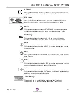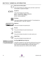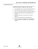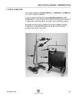
SECTION 1 GENERAL INFORMATION
0855849enf 6/08
7
field
A specific manipulatable area within the job file.
flash
The process of writing the control software to nonvolatile memory.
holding chamber
The lower portion of the ink delivery module where ink is heated and stored.
host computer
The computer that contains the data that is downloaded to the coder. This
computer may contain software such as CimControl and CoLOS Create.
ILS
Ink Level Sensor. An electrical device used to monitor ink levels. Formerly
called LOIS (Low On Ink Sensor).
image
The displayed or printed representation of the information, composed of one
or more fields, from one printhead. The images for all printheads connected
to the coder are called the label.
ink bottle
Container of solid ink that the operator inserts through the ink door.
ink delivery module
The assembly that stores, heats, and pumps the ink.
jet array
The area on the front of the printhead that ejects droplets of ink onto the
customer’s product.
jet test
The process of printing a pattern used to confirm the proper operation of all
jets.
job
See job file.
job file
A set of parameters that determines what, how, where, and when images
will print. Before printing, the image data must be downloaded to the coder
from the host computer.
label
The displayed or printed images from all printheads connected to the coder.
local
The storage of job files on the coder, after having been downloaded from the
host computer.
LOIS
Low On Ink Sensor. See ILS.
melting chamber
The upper portion of the ink delivery module that melts the ink from the ink
bottle.
OCU
Optional Control Unit.
offline
The state of the coder when not printing.
online
The state of the coder when printing.
optional control unit
An optional control device that can be connected to the coder, which allows
up to two bar code readers and one product ID reader to be connected.
PH
Printhead. Specific printheads are abbreviated as PH1, PH2, PH3, and PH4.
Summary of Contents for Markem-Imaje 5000 Series
Page 1: ...o p e r a t i o n g u i d e ...
Page 2: ......
Page 4: ...iv 0855849enf 6 08 ...
Page 7: ...Model 5200 5400 Operation Guide SECTION 1 General Information ...
Page 8: ......
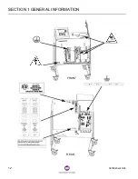
Page 18: ...SECTION 1 GENERAL INFORMATION 12 0855849enf 6 08 FRONT REAR ...
Page 24: ......
Page 25: ...Model 5200 5400 Operation Guide SECTION 2 Basic Operation ...
Page 26: ......
Page 38: ......
Page 39: ...Model 5200 5400 Operation Guide SECTION 3 Printing ...
Page 40: ......
Page 55: ...Model 5200 5400 Operation Guide SECTION 4 Cleaning and Care ...
Page 56: ......
Page 61: ...Model 5200 5400 Operation Guide SECTION 5 Troubleshooting ...
Page 62: ......
Page 67: ...User Documentation Department ...


