


32
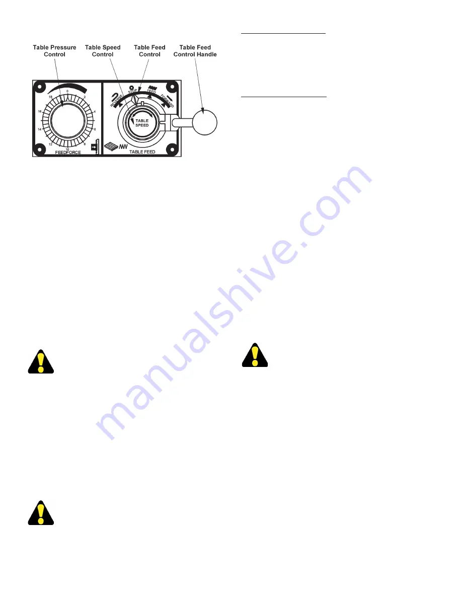
Table Controls.
•
Table Speed.
This dial located in the center of the
Table Feed
control regulates the table speed. Turn
the dial
clockwise
to “increase” table feed speed,
counterclockwise
to “decrease” it. This operates
in the “feed” position only.
GLIDE TABLE
1.
This non-tilting worktable option has a 25.39 by
32.63 inch (644.9 by 828.8 mm) worktable and table
travel of 18.00 inches (457.2 mm). Load capacity
is 250 pounds (113.4 kg).
2.
The workpiece is securely clamped to the table.
The operator then holds the handle in front of the
table and manually pushes the table with the work-
piece through the saw band. The handle also acts
as a workstop if desired.
DO NOT force workpiece through the saw
band.
3.
A thumbscrew located in the lower right under the
worktable locks the worktable in place to allow load-
ing and unloading of stock. Loosen the thumbscrew
completely for the worktable to move freely.
4.
The handle must be removed for saw band
changing.
OPTIONAL SAW GUIDES
1.
The following optional saw guides may be used to
help increase productivity and economy.
Information and availability of all DoALL saw
bands and guides can be obtained from a
DoALL sales representative.
Insert Type Saw Guides
1.
Insert type saw guides are designed for lower range
band speeds. See the
“Operation”
section of this
manual for use and adjustments for these saw
guides.
Roller Type Saw Guides
1.
Roller type saw guides are designed for high range
band speeds. See the
“Operation”
section of this
manual for use and adjustments for these saw
guides.
EXTRA WORK HEIGHT
1.
The factory installed extra work height allows
maximum cutting capacity up to 42 inches
(1066.8 mm). Machines with this option have
an auxiliary post support, plus a slightly different
frame weldment, post guarding, and hydraulic
post cylinder from those shown elsewhere in this
manual.
HYDRAULIC BAND TENSION
1.
A factory installed cylinder mounted next to the upper
bandwheel spindle applies the correct tension to the
band and controlled by a selector switch on or near
the control box enclosure.
2.
This option eliminates the need to physically climb
up on the machine. This especially helpful with
machines of large work heights.
Optional hydraulic band tension is factory set.
DO NOT adjust the handwheel if supplied!
BAND LUBRICATOR
1.
For machines without the mist lubricated saw guides,
this option is for lubricating the saw band and sawing
area during the sawing process.
2.
See the instructions sent with the unit for information
on operation and adjustments.
DUST COLLECTOR
1.
See the literature sent with the unit for information
on installation, operation, maintenance and
adjustments.
HYDRAULIC TABLES (Continued....)
Summary of Contents for ZV-3620
Page 1: ...ZV 3620 Serial No 565 03101 to Band Sawing Machine Instruction Manual...
Page 6: ...2 MACHINE DIMENSIONS Continued INCHES 03 MILLIMETERS 1 mm FLOOR PLAN With HMD HYDRAULIC TABLE...
Page 9: ...5 MACHINE FEATURES FRONT VIEW...
Page 10: ...6 MACHINE FEATURES Continued FRONT VIEW With HMD HYDRAULIC TABLE...
Page 11: ...7 MACHINE FEATURES Continued REAR VIEW...
Page 12: ...8 MACHINE FEATURES Continued REAR VIEW With HMD HYDRAULIC TABLE...
Page 25: ...21 LUBRICATION DIAGRAM HMD TABLE OPTION REAR VIEW...


