


23
2.
To adjust system pressure:
(a)
Loosen the jam nut
counterclockwise
on the adjusting screw;
(b)
Start
the hydraulic motor by pushing the
Hydraulic Start
button;
(c)
Looking at the pressure gauge, turn the
adjusting screw
in
(clockwise)
to increase pressure,
out (counterclockwise)
to decrease it.
Pump Repair & Replacement
1.
DO NOT attempt to repair the hydraulic pump.
Return it to the factory for repair or replacement. Be
sure to specify the correct pump model and serial
numbers when returning the unit.
After the pump has been primed, run it
for several minutes while operating the
machine’s controls to purge entrapped air
from the pump and system. Check for oil
leaks while the system is being operated.
HYDRAULIC TABLE (Optional)
Bleeding Air From The System
1.
Run the machine for at least 30 minutes or until oil
is warm. Then:
(a)
Position the adjustable table
stops, located on the side of the table, to give full
table travel;
(b)
Place the
Table Feed Control
in
“FORWARD” to move the table cylinder rod to its
extended position;
(c)
Remove the two (2) jam nuts
and spacer shown in the illustration.
Support the rod end of the table cylinder as
the rod is pulled out of the table bracket.
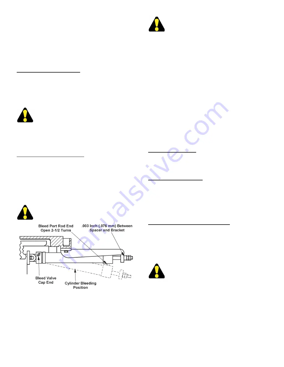
Bleeding Air From the Hydraulic System.
2.
Attach a length of plastic tubing to the bleed valve
on the rod end of the cylinder and route it into the
reservoir through the dip stick opening. Next:
(a)
Open the bleed valve on the cap end of the cylinder;
(b)
Move the
Table Feed Control
to “REVERSE”
and retract the cylinder.
Be certain to close the bleed port opposite the
end you are bleeding.
3.
Allow the cylinder to hang down to provide access
to the bleed port on the top of the rod end cap.
Then:
(a)
Close the bleed valve on the cap end
of the cylinder;
(b)
With a container under the
rod end of the cylinder, open the bleed port 2-1/2
turns
counterclockwise
;
(c)
Move the
Table Feed
Control
in “FORWARD” to fully extend the cylinder
rod;
(d)
Repeat steps 2 and 3 until all air is purged
from the system.
4.
Reinstall the table cylinder rod with spacer and jam
nuts, as shown in the illustration. Allow .003 inch
(.076 mm) clearance between the spacer and the
table bracket.
4.
See the
"Adjustment Summary"
for information on
all hydraulic adjustment procedures.
SAW GUIDES
Pivot Back-Up Inserts
1.
Reverse pivot back-up inserts for additional wear
life, then replace when all surfaces are worn.
Roller Back-Up Bearings
1.
These bearings are sealed and packed for life with
a special lubricant. They can be replaced by:
(a)
Removing the snap ring;
(b)
Pulling out the bearing
and shaft;
(c)
New bearings are easily installed with
a light press fit.
Automatic Mist Lubricated (Optional)
1.
Keep reservoir full and hoses clear. Follow the
manufacturer’s maintenance instructions for the
lubricator.
MACHINE CLEANING
Stop the machine when cleaning the machine
or opening bandwheel doors or covers.
1.
Keep the machine and its parts as clean as possible
to prevent excessive wear and damage.
3.
Metal chips and other waste materials may
collect around areas such as: saw guides,
table surface, T-slots, bandwheels, slides, etc.
Remove these materials as soon as possible.
The
DoALL Company recommends removing chip
collections at least twice per each eight (8) hour
shift, and more often with heavier use.
HYDRAULIC SYSTEM (Continued....)
Summary of Contents for ZV-3620
Page 1: ...ZV 3620 Serial No 565 03101 to Band Sawing Machine Instruction Manual...
Page 6: ...2 MACHINE DIMENSIONS Continued INCHES 03 MILLIMETERS 1 mm FLOOR PLAN With HMD HYDRAULIC TABLE...
Page 9: ...5 MACHINE FEATURES FRONT VIEW...
Page 10: ...6 MACHINE FEATURES Continued FRONT VIEW With HMD HYDRAULIC TABLE...
Page 11: ...7 MACHINE FEATURES Continued REAR VIEW...
Page 12: ...8 MACHINE FEATURES Continued REAR VIEW With HMD HYDRAULIC TABLE...
Page 25: ...21 LUBRICATION DIAGRAM HMD TABLE OPTION REAR VIEW...


