Maintenance Manual Removal and Replacement
____________________________________________________________________________________________
4.3.18 Carriage Assy
CAUTION : Before starting with this procedure, put the carriage assy in the maximum
distance from the platen assy to avoid any print head mask damage.
1) Remove the Main Rear and Front Covers (refer to chapter 4.3.4 and 4.3.5).
2) Remove the print head (refer to chapter 4.3.3).
3) Remove the carriage motor assy (refer to chapter 4.4.12).
4) Remove the AGA support and the AGA sector on the left side part.
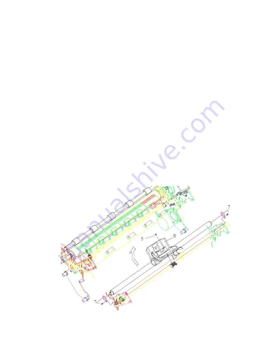
5) Unscrew the screw securing the carriage belt to the carriage assy.
6) Unscrew the two screws securing the main shaft retainer to the left side of the
mechanism.
7) Unscrew the two screws securing the main shaft retainer to the right side of the
mechanism.
8) Gently rotate the carriage assy with the front bar upward and extract it from the rear
bar.
Replace the carriage assy following the above instructions in reverse order.
NOTICE: the carriage assy replacement requires the appropriate print head gap and
carriage belt adjustment procedures (refer to chapter 5). Slowly introduce the
front bar into the carriage holes paying attention to the oil-felt inside it.
Figure 4.18 Carriage Assy
____________________________________________________________________________________________
LA400 Multiprinter 4. 22 ER-LA400-SV


