26
GB
They connect and disconnect the corresponding zone and put the zone into test mode.
Pressing once puts the corresponding zone into test mode, while pressing it a second
time disconnects the corresponding area.
In disconnected state, the disable led and the corresponding fault/disable/test led is
activated.
6.3.2- Test key (B)
Pressing this button for one second causes all the LED to come on for a few seconds;
if there is any kind of fault in the power supply, it will show up immediately.
In the case we were in test mode, pushing this key we will come back to the restin
state.
6.3.3- Activate sounders (C)
The pressing of this key causes the immediate activation of the sounders. This control
overrides any sounder delay that has been programmed.
The pressing this button connects the sounders, if they were previously disconnected,
in which case the sounders/fault/cancelled LED will light up.
6.3.4- Silence sounders (D)
Pressing this button deactivates the sounders when they are activated and disconnects
them when they have not been activated. In the latter case, the general disconnection
and sounders disconnection LED will come on.
6.3.5- Silence buzzer key (E)
This key silences the buzzer when it is active, and the silence buzzer indicator lights.
When the buzzer is re-activated, the silence buzzer indicator turns off.
6.3.6- Reset key (F)
Pressing this button causes the system to return to the normal condition.
6.3.7- Keypad locking key (G)
When the key is in the closed position, the keypad is locked and cannot be used. For
pressing buttons to take effect, you must put the key in the open position.
6.3.8- Key for the selection of the extinction block operating mode (H)
It selects the operating mode for the extinction block. The operating modes allowed
are:
Summary of Contents for CCD-103
Page 1: ...GB ES ES GUIDE MANUAL FR 3 Zones Conventional fire extinguishant control panel IT ...
Page 2: ......
Page 3: ...ES ES Central Convencional de 3 Zonas de detección y 1 Extinción MANUAL DEL USUARIO ...
Page 4: ......
Page 6: ......
Page 14: ...12 ES 4 Guía de conexionado de la PCB ...
Page 44: ......
Page 45: ...GB GUIDE MANUAL 3 Zones Conventional fire extinguishant control panel ...
Page 46: ......
Page 48: ......
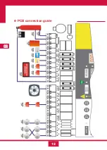
Page 56: ...12 GB 4 PCB connection guide ...
Page 86: ......
Page 87: ...FR FR Centrale conventionnelle à 3 zones de détection et 1 zone d extinction MODE D EMPLOI ...
Page 88: ......
Page 90: ......
Page 98: ...FR 12 4 Guide de branchement de la PCB carte de circuit imprimé ...
Page 128: ......
Page 129: ...IT Central Convencional de 3 Zonas de detección y 1 Extinción MANUAL UTENTE ...
Page 130: ......
Page 132: ......
Page 140: ...12 IT 4 Guía de conexionado de la PCB ...
Page 170: ...55310300 2014 10 14 ...

