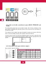
24
GB
6.1.19- State 2 Sounder Output ( Fault, Activation) (19)
•
The Left yellow LED indicates there is a fault in the output.
•
The right red LED indicates the output is active.
6.1.20- State 1 Sounder Output ( Fault, Activation) (20)
•
The Left yellow LED indicates there is a fault in the output.
•
The right red LED indicates the output is active.
6.1.21- Triggering button input ( Fault, Activation) (21)
•
The Left yellow LED indicates there is a fault in the input.
•
The right red LED indicates the input is active.
6.1.22- Stop button input ( Fault, Activation) (22)
•
The Left yellow LED indicates there is a fault in the input.
•
The right red LED indicates the input is active.
6.1.23- Pause button input ( Fault, Activation) (23)
•
The Left yellow LED indicates there is a fault in the input.
•
The right red LED indicates the input is active.
6.1.24- Door Surveillance input ( Fault, Activation) (24)
•
The Left yellow LED indicates there is a fault in the input.
•
The right red LED indicates the input is active.
6.1.25- Bottle 1 Surveillance input ( Pressure fault) (25)
•
Blinking:
There is a fault in the input.
6.1.26- Bottle 2 Surveillance input ( Flow fault) (26)
•
Blinking:
There is a fault in the input.
6.1.27- Pre activated state (27)
•
Fixed:
The system is in pre activated state.
6.1.28- Activated state(28)
•
Fixed:
The system is in activated state.
6.1.29- Triggered state(29)
•
Blinking:
The system is performing the bottle activation.
•
Fixed:
The system has finished the activation of the bottle output.
Summary of Contents for CCD-103
Page 1: ...GB ES ES GUIDE MANUAL FR 3 Zones Conventional fire extinguishant control panel IT ...
Page 2: ......
Page 3: ...ES ES Central Convencional de 3 Zonas de detección y 1 Extinción MANUAL DEL USUARIO ...
Page 4: ......
Page 6: ......
Page 14: ...12 ES 4 Guía de conexionado de la PCB ...
Page 44: ......
Page 45: ...GB GUIDE MANUAL 3 Zones Conventional fire extinguishant control panel ...
Page 46: ......
Page 48: ......
Page 56: ...12 GB 4 PCB connection guide ...
Page 86: ......
Page 87: ...FR FR Centrale conventionnelle à 3 zones de détection et 1 zone d extinction MODE D EMPLOI ...
Page 88: ......
Page 90: ......
Page 98: ...FR 12 4 Guide de branchement de la PCB carte de circuit imprimé ...
Page 128: ......
Page 129: ...IT Central Convencional de 3 Zonas de detección y 1 Extinción MANUAL UTENTE ...
Page 130: ......
Page 132: ......
Page 140: ...12 IT 4 Guía de conexionado de la PCB ...
Page 170: ...55310300 2014 10 14 ...

