GB
23
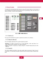
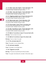
6.1.17- Bottle Output ( Fault, Activation) (17)
•
The Left yellow LED indicates there is a fault in the output.
•
The right red LED indicates the output is active.
6.1.18- Sign Output ( Fault, Activation) (18)
•
The Left yellow LED indicates there is a fault in the output.
•
The right red LED indicates the output is active.
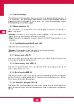
6.1.11- Fault / Disablement Sounder LED (11)
Yellow indicator associated with the outputs of sounders:
•
Blinking:
There is a sounder fault.
•
Fixed:
The sounders are disabled.
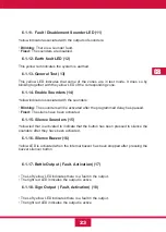
6.1.12- Earth fault LED (12)
This yellow led indicates the system is earthed.
6.1.13- General Test (13)
This yellow LED indicates that some of the zones are in test mode, It does so by
blinking together with the yellow LED of the corresponding zone.
6.1.14- Enable Sounders (14)
Yellow indicator associated with the sounders:
•
Blinking:
The sounders will be activated after the programmed delay has passed.
•
Fixed:
The sirens have been activated.
6.1.15- Silence Sounders (15)
Yellow led that is activated to indicate that the button has been pressed to silence the
sounders after they have been activated.
6.1.16- Silence Buzzer (16)
Yellow LED is activated when the internal buzzer has been stopped after pressing the
buzzer silencer button.
Summary of Contents for CCD-103
Page 1: ...GB ES ES GUIDE MANUAL FR 3 Zones Conventional fire extinguishant control panel IT ...
Page 2: ......
Page 3: ...ES ES Central Convencional de 3 Zonas de detección y 1 Extinción MANUAL DEL USUARIO ...
Page 4: ......
Page 6: ......
Page 14: ...12 ES 4 Guía de conexionado de la PCB ...
Page 44: ......
Page 45: ...GB GUIDE MANUAL 3 Zones Conventional fire extinguishant control panel ...
Page 46: ......
Page 48: ......
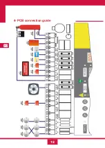
Page 56: ...12 GB 4 PCB connection guide ...
Page 86: ......
Page 87: ...FR FR Centrale conventionnelle à 3 zones de détection et 1 zone d extinction MODE D EMPLOI ...
Page 88: ......
Page 90: ......
Page 98: ...FR 12 4 Guide de branchement de la PCB carte de circuit imprimé ...
Page 128: ......
Page 129: ...IT Central Convencional de 3 Zonas de detección y 1 Extinción MANUAL UTENTE ...
Page 130: ......
Page 132: ......
Page 140: ...12 IT 4 Guía de conexionado de la PCB ...
Page 170: ...55310300 2014 10 14 ...

