GB
13
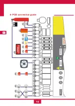
The extinguishing panel connections are divided into two blocks.
Conventional detection block, with the following inputs and outputs:
- Zone Inputs 1,2 and 3.
- Alarm and Fault relay outputs.
- General alarm sounder output.
- 24 V aux. output.
- Exterior input.
- Ventilation relay output.
Extinction block, with the following inputs and outputs:
- Extinction bottle solenoid output.
- Warning sign “Don’t enter extinction active” output.
- State 1 and 2 sounder outputs.
- Triggering, stop and hold MCP inputs.
- Door surveillance and 2 bottle surveillance inputs.
.
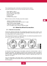
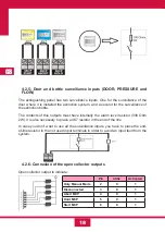
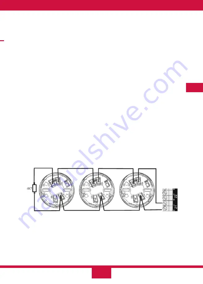
As indicated in the drawing above, the positive connects to contact number 1 both in
the input and output. The negative connects to the line input at contact 4 and leaves
through contact 3 to the following detector. At the end of the line you must place a
4K7 end-of-line. Remember that the maximum number of detectors per zone is 32
detectors or 32 MCP.
If you are not going to use all the zones, it is necessary to connect the end-of-line
resistor (4.7kOhm) at the terminals of the not used zone in order to avoid a fault signal
from the system.
4.1- Detection Block Connection
4.1.1- Detectors Connection
In the factory default configuration, the extinguishing panel has 3 zones. Zones 1 and
2 work as crossed zones in order to activate the automatic extinction process. Zone 3
is an independent zone for adjacent zones.
The extinguishant fire panel is compatible with the conventional range detectors and it
will not work properly with another detectors
Summary of Contents for CCD-103
Page 1: ...GB ES ES GUIDE MANUAL FR 3 Zones Conventional fire extinguishant control panel IT ...
Page 2: ......
Page 3: ...ES ES Central Convencional de 3 Zonas de detección y 1 Extinción MANUAL DEL USUARIO ...
Page 4: ......
Page 6: ......
Page 14: ...12 ES 4 Guía de conexionado de la PCB ...
Page 44: ......
Page 45: ...GB GUIDE MANUAL 3 Zones Conventional fire extinguishant control panel ...
Page 46: ......
Page 48: ......
Page 56: ...12 GB 4 PCB connection guide ...
Page 86: ......
Page 87: ...FR FR Centrale conventionnelle à 3 zones de détection et 1 zone d extinction MODE D EMPLOI ...
Page 88: ......
Page 90: ......
Page 98: ...FR 12 4 Guide de branchement de la PCB carte de circuit imprimé ...
Page 128: ......
Page 129: ...IT Central Convencional de 3 Zonas de detección y 1 Extinción MANUAL UTENTE ...
Page 130: ......
Page 132: ......
Page 140: ...12 IT 4 Guía de conexionado de la PCB ...
Page 170: ...55310300 2014 10 14 ...

