background image

Chapter 5  Troubleshooting 

|


Revision July 2008, EG03, SW V1.06 

5-7

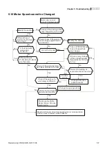
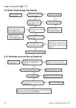
5.10 Motor Speed cannot be Changed 


Motor can run but
cannot change speed

Yes

Yes

Yes

Yes

Yes

Yes

Yes

Yes

Yes

Yes

No

No

No

No

No

No

No

No

No

No

Check if the setting of the 
max. frequency is too low

Check to see if frequency is 
out of range (upper/lower) 

boundaries

Modify the setting

Modify the setting

Yes

No

Yes

If the setting of 

Pr.05-17toPr.05-31
is too high 

Yes

If finished with 
executing
Pr.05-15

If the setting of
Pr.05-00 to Pr.05-14 

are the same

Is it in PLC mode

Press UP/DOWN key

to see if speed has 
any change

If there is any change
of the signal that sets

frequency (0~10V and
0~1A)

Check if the wiring between

MI1~MI4 to DCM is correct

Correct

  wiring

Check if frequency for 

each step is different

Check if the wiring of 
external terminal is correct

Change frequencysetting

Check if accel./decel. 

time is set correctly

Please set suitable

accel./decel. time by
load inertia

Maybe AC motor drive has malfunction or misoperation

due to noise. Please contact DELTA.

Change defective

potentiometer


Summary of Contents for AC Motor Drive VFD-G

Page 1: ......

Page 2: ......

Page 3: ......

Page 4: ...please contact your dealer PLEASE READ PRIOR TO INSTALLATION FOR SAFETY DANGER 1 AC input power must be disconnected before any wiring to the AC motor drive is made 2 A charge may still remain in the...

Page 5: ...motor drive in a place subjected to high temperature direct sunlight high humidity excessive vibration corrosive gases or liquids or airborne dust or metallic particles 3 Only use AC motor drives with...

Page 6: ...ries Number Explanation 1 3 1 1 4 Drive Frames 1 3 1 2 Appearances 1 3 1 3 Remove Instructions 1 3 1 3 1 Remove Keypad 1 3 1 3 2 Remove Front Cover 1 3 1 4 Lifting 1 3 1 5 Preparation for Installation...

Page 7: ...eypad VFD PU01 3 3 3 1 3 VFD PU01 Dimensions 3 3 3 1 4 Reference Table for the LED Display of the Digital Keypad 3 3 3 2 Operation Method 3 3 3 3 Trial Run 3 3 Chapter 4 Parameters 4 3 4 1 Summary of...

Page 8: ...mation 6 3 6 1 1 Common Problems and Solutions 6 3 6 1 2 Reset 6 3 6 2 Maintenance and Inspections 6 3 Appendix A Specifications A 3 Appendix B Accessories B 3 B 1 All Brake Resistors Brake Units Used...

Page 9: ...nation of Display Message B 3 B 6 3 PU06 Operation Flow Chart B 3 Appendix C How to Select the Right AC Motor Drive C 3 C 1 Capacity Formulas C 3 C 2 General Precaution C 3 C 3 How to Choose a Suitabl...

Page 10: ...number of your order 1 1 1 Nameplate Information Example for 10HP 7 5kW 3 phase 460V AC drive MODE VFD075F43A G INPUT 3PH 380 480V 50 60Hz 19 0A OUTPUT 3PH 0 480V 18A 14kVA 10HP Freq Range 0 1 120 00...

Page 11: ...r 1 1 4 Drive Frames Frame Power Range Models C 7 5 20HP 5 5 15kW VFD055F43B G VFD075F43B G VFD110F43A G VFD150F43A G D 25 40HP 18 5 30kW VFD185F43A G VFD220F43A G VFD300F43A G E 50 75HP 37 55kW VFD37...

Page 12: ...Chapter 1 Introduction Revision July 2008 EG03 SW V1 06 1 3 50 125HP 37 90kW Frame E E1 150 215HP 110 160kW Frame G 250 300HP 185 220kW Frame H...

Page 13: ...r 1 Introduction 1 4 Revision July 2008 EG03 SW V1 06 1 3 Remove Instructions 1 3 1 Remove Keypad 7 5 20HP 5 5 15kW Frame C 25 40HP 18 5 30kW Frame D 50 125HP 37 90kW Frame E E1 150 215HP 110 160kW Fr...

Page 14: ...Chapter 1 Introduction Revision July 2008 EG03 SW V1 06 1 5 250 300HP 185 220kW Frame H 1 3 2 Remove Front Cover 7 5 20HP 5 5 15kW Frame C 25 40HP 18 5 30kW Frame D...

Page 15: ...Chapter 1 Introduction 1 6 Revision July 2008 EG03 SW V1 06 50 125HP 37 90kW Frame E E1 150 215HP 110 160kW Frame G 250 300HP 185 220kW Frame H...

Page 16: ...Chapter 1 Introduction Revision July 2008 EG03 SW V1 06 1 7 1 4 Lifting Please carry only fully assembled AC motor drives as shown in the following For 50 125HP Frame E E1 Step 1 Step 2 Step 3 Step 4...

Page 17: ...Chapter 1 Introduction 1 8 Revision July 2008 EG03 SW V1 06 For 150 215HP Frame G Step 1 Step 2 Step 3 Step 4...

Page 18: ...Chapter 1 Introduction Revision July 2008 EG03 SW V1 06 1 9 For 250 300HP Frame H Step 1 Step 2 Step 3 Step 4...

Page 19: ...allation Site Altitude 1000m Operation Vibration 20Hz 9 80 m s2 1G max 20 50Hz 5 88 m s2 0 6G max Temperature 20 C 60 C 4 F 140 F Relative Humidity 90 no condensation allowed Atmosphere pressure 86 10...

Page 20: ...y rise to 90 C when running The material on which the AC motor drive is mounted must be noncombustible and be able to withstand this high temperature 6 When AC motor drive is installed in a confined s...

Page 21: ...5 12 205 4 8 08 10 0 0 39 NOTE Frame C VFD055F43B G VFD075F43B G VFD110F43A G VFD150F43A G Frame D VFD185F43A G VFD220F43A G VFD300F43A G W1 W D H H1 F H2 Unit mm inch Frame W W1 H H1 H2 D F E 370 0 1...

Page 22: ...H2 D F G 425 0 16 73 381 0 15 00 850 0 33 46 819 5 32 26 764 0 30 08 264 0 10 39 6 5 0 26 NOTE Frame G VFD1100F43C G VFD1320F43A G VFD1600F43A G Unit mm inch Frame W W1 H H1 H2 D1 F H 547 0 21 54 480...

Page 23: ...Chapter 1 Introduction 1 14 Revision July 2008 EG03 SW V1 06 This page intentionally left blank...

Page 24: ...o the AC motor drive and the motor nameplate for electrical data The Line Fuse Specification in Appendix B lists the recommended fuse part number for each VFD G Series part number These fuses or equiv...

Page 25: ...efore opening the AC motor drive 2 Only qualified personnel familiar with AC motor drives is allowed to perform installation wiring and commissioning 3 Make sure that the power is off before doing any...

Page 26: ...ed Circuit when power supply is turned OFF by a fault output MC VFD G E F Multi step1 Multi step2 Multi step3 Multi step4 Factory Setting Multi function input terminals Factory setting disable Multi f...

Page 27: ...step3 Multi step4 Factory Setting Multi function input terminals Factory setting disable Multi function indication output contacts NOTE 1 3 are optional Jumper DC Reactor Optional Brake Resistor Optio...

Page 28: ...prevent erroneous actions 2 Please use shield wire for the control wiring and not to expose the peeled off net in front of the terminal 3 Please use the shield wire or tube for the power wiring and gr...

Page 29: ...eactor 8 The AC motor drive electric welding machine and the greater horsepower motor should be grounded separately 9 Use ground leads that comply with local regulations and keep them as short as poss...

Page 30: ...n from AC line disturbances surges switching spikes short interruptions etc AC line reactor should be installed when the power supply capacity is 500kVA or phase lead reactor will be switched And the...

Page 31: ...U T1 V T2 W T3 IM 3 Motor MC VFD G Jumper DC Reactor Optional Brake Resistor Optional P N B1 B2 VFDB Brake Unit Optional NFB NFB R L1 S L2 T L3 For 460V series 25hp and above Terminal Symbol Explanati...

Page 32: ...not less than 0 1 second detection time to avoid nuisance tripping For the specific GFCI of the AC motor drive please select a current sensor with sensitivity of 30mA or above Do NOT run stop AC motor...

Page 33: ...deta ils Fo r 460V series 25HP an d abo ve Connect a brake resistor or brake unit in applications with frequent deceleration ramps short deceleration time too low brake torque or requiring increased...

Page 34: ...tivation current is 16mA OFF leakage current tolerance is 10 A 24V DC Voltage Source 24V 20mA used for Source mode DCM Digital Signal Common Used as common for digital inputs and used for Sink mode AF...

Page 35: ...ly affected by external noise Use shielded wiring and keep it as short as possible 20m with proper grounding If the noise is inductive connecting the shield to terminal AC1 AC2 can bring improvement I...

Page 36: ...angle The AC motor drive control wiring should be properly installed and not touch any live power wiring or terminals NOTE If a filter is required for reducing EMI Electro Magnetic Interference insta...

Page 37: ...43B G VFD075F43B G VFD110F43A G VFD150F43A G POWER IM MOTOR 3 Control Terminal Torque 4Kgf cm 3 in lbf Wire 12 24 AWG Power Terminal Torque 30Kgf cm 26 in lbf Wire 12 8 AWG Wire Type Stranded copper o...

Page 38: ...M POWER S L2 R L1 DC DC T L3 1 2 MOTOR Control Terminal Torque 4Kgf cm 3 in lbf Wire 12 24 AWG Power Terminal Torque 30Kgf cm 26 in lbf Wire 8 2 AWG Wire Type Stranded copper only 75 C NOTE If wiring...

Page 39: ...60 HP VFD370F43A G VFD450F43A G R L1 1 2 S L2 T L3 U T1 V T2 2 T3 POWER IM MOTOR 3 POWER ALARM CHARGE Control Terminal Torque 4Kgf cm 3 in lbf Wire 12 24 AWG Power Terminal Torque 57kgf cm 49 5 in lbf...

Page 40: ...F43C G W T3 S L2 R L1 T L3 2 1 U T1 V T2 173in lbf Screw Torque 200kgf cm POWER IM MOTOR 3 POWER ALARM CHARGE Control Terminal Torque 4Kgf cm 3 in lbf Wire 12 24 AWG Power Terminal Torque 200kgf cm 17...

Page 41: ...MOTOR DC 3 V T2 S L2 R L1 2 T L3 1 U T1 W T3 Control Terminal Torque 4Kgf cm 3 in lbf Wire 12 24 AWG Power Terminal Torque 300kgf cm 260 in lbf Wire 1 0 AWG 2 300 MCM 2 Wire Type Stranded copper only...

Page 42: ...DC DC POWER U T1 T L3 R L1 S L2 W T3 V T2 Control Terminal Torque 4Kgf cm 3 in lbf Wire 12 24 AWG Power Terminal Torque 408kgf cm 354 in lbf Wire 500 MCM max Wire Type Stranded copper only 75 C NOTE I...

Page 43: ...xplanation for Analog Input Terminal When using analog input please pay attention to the jumper on the control board Whether the jumper is cut off or not is determined by analog input type voltage or...

Page 44: ...1A please plug into the left two pins See the red mark and make sure the jumper is connected well See what the following yellow arrows point at 2 When using analog voltage input 0 10V please transfer...

Page 45: ...Chapter 2 Installation and Wiring 2 22 Revision July 2008 EG03 SW V1 06 This page intentionally left blank...

Page 46: ...he numerical data such as Master Frequency JOG By pressing JOG key Initiates jog operation MODE Changes between different display mode Display Message Descriptions Display the AC drive Master Frequenc...

Page 47: ...2 How to Operate the Digital Keypad VFD PU01 MODE MODE MODE MODE MODE MODE START U F H Selecting mode START To shift data To modify data Setting direction or Setting parameters U F H U F H U F H GO S...

Page 48: ...he LED Display of the Digital Keypad Digit 0 1 2 3 4 5 6 7 8 9 LED Display English alphabet A b Cc d E F G Hh Ii Jj LED Display English alphabet K L n Oo P q r S Tt U LED Display English alphabet v Y...

Page 49: ...tting for details Parameter setting Pr 02 00 03 Refer to the communication address 2000H setting for details Parameter setting Pr 02 01 03 04 U F H STOP RUN REV VFD PU01 FWD JOG JOG RUN RESET STOP VFD...

Page 50: ...STOP key 4 Check following items Check if the motor direction of rotation is correct Check if the motor runs steadily without abnormal noise and vibration Check if acceleration and deceleration are sm...

Page 51: ...Chapter 3 Keypad and Start Up 3 6 Revision July 2008 EG03 SW V1 06 This page intentionally left blank...

Page 52: ...need for re adjustment during operation The 10 groups are as follows Group 0 User Parameters Group 1 Basic Parameters Group 2 Operation Method Parameters Group 3 Output Function Parameters Group 4 Inp...

Page 53: ...n Failure 10 ocA current exceed during Acceleration 11 ocd current exceed during Deceleration 12 ocn current exceed during Steady State 13 GFF Ground Fault 14 Lv Low voltage 15 CF1 abnormal input data...

Page 54: ...is blink and FWD led is on 10 Rev led is on and FWD led is blink 11 Rev led is on and FWD led is off Bit 5 7 Reserved Bit 8 Master frequency source via communication interface Bit 9 Master frequency s...

Page 55: ...40 0 01 03 Mid point Frequency 0 10 120 Hz 3 00 01 04 Mid point Voltage 0 2V 510 0V 11 0 01 05 Minimum Output Frequency 0 10 20 00 Hz 3 00 01 06 Minimum Output Voltage 0 2V 100 0V 11 0 01 07 Upper Bou...

Page 56: ...Command 00 via keypad 01 via analog input AI1 02 via analog input AI2 03 via RS485 serial communication 04 via External Reference 00 02 01 Source of Operation Command 00 Controlled by the digital key...

Page 57: ...Bit2 0 Fwd LED 1 Rev LED Bit3 5 000 1st 7 step 001 2nd 7 step 010 3rd 7 step 011 4th 7 step 100 5th 7 step Bit6 7 Reserved 00 02 09 Special Display 00 A displays output current of AC drive 01 U displa...

Page 58: ...ion 17 PID Feedback Error Indication 18 PLC Program Running 19 PLC Program Step Completed 20 PLC Program Completed 21 PLC Operation Paused 01 03 01 Reserved 03 02 Master Frequency Attained 1 0 00 160...

Page 59: ...NC input 13 Increase Frequency 14 Decrease Frequency 15 Emergency stop NO 16 Emergency stop NC 17 KEYPAD open EXT close 18 PID disable 19 Run PLC Program 20 Pause PLC Program 21 1st Output Frequency...

Page 60: ...I2 0 00 10 00 Sec 0 50 04 25 Summation of External Frequency Sources 00 Disabled 01 AI1 AI1 Gain AI2 AI2 Gain 02 AI1 AI1 Gain AI2 AI2 Gain 03 AI1 AI1 Gain AI2 AI2 Gain 04 Reserved 05 Communication mas...

Page 61: ...0 00 160 00 Hz 0 00 05 09 10th Step Speed Frequency 0 00 160 00 Hz 0 00 05 10 11th Step Speed Frequency 0 00 160 00 Hz 0 00 05 11 12th Step Speed Frequency 0 00 160 00 Hz 0 00 05 12 13th Step Speed Fr...

Page 62: ...4 0 0 to 65500 Sec 0 0 6550 0 Sec 0 0 05 31 Time Duration Step 15 0 0 to 65500 Sec 0 0 6550 0 Sec 0 0 05 32 Time Unit Settings 00 1 Sec 01 0 1 Sec 00 Group 6 Protection Function Parameters Parameter F...

Page 63: ...d Most Recent Fault Record 00 06 14 Fourth Recent Fault Record 00 No Fault 01 Oc over current 02 Ov over voltage 03 OH over temperature 04 OL over load 05 oL1 over load 1 06 EF external fault 07 Occ I...

Page 64: ...set 00 65535 09 Reset parameters 50Hz 380 10 Reset parameters 60Hz 440 00 06 16 Parameter Protection Password Input 00 65535 00 06 17 Parameter Protection Password Setting 00 65535 00 No password prot...

Page 65: ...meters Parameter Functions Settings Factory Setting Customer 08 00 DC Braking Current Level 00 100 00 08 01 DC Braking Time during Start up 0 0 60 0 Sec 0 0 08 02 DC Braking Time during Stopping 0 00...

Page 66: ...Regulation AVR 00 AVR function enabled 01 AVR function disabled 02 AVR function disabled for deceleration 00 08 19 Software Setting of the Braking Level the action level of the braking resistor 740V 8...

Page 67: ...direction command Bit6 7 00 1st step accel decel speed 01 2nd step accel decel speed 10 3rd step accel decel speed 11 4th step accel decel speed Bit8 11 0000 Master speed 0001 1st step speed 0010 2nd...

Page 68: ...10 03 Proportional Gain P 0 0 10 0 1 0 10 04 Integral Time I 0 00 100 00 Sec 1 00 10 05 Differential Time D 0 00 1 00 Sec 0 00 10 06 Upper Bound for Integral Control 00 200 100 10 07 Primary Low Pass...

Page 69: ...cute DC brake before start up 08 00 08 01 Energy Saving Applications Purpose Functions Related Parameters Punching machines and precision machinery Energy saving and less vibrations Energy saving when...

Page 70: ...OSE RUN EF OPEN STOP REV OPEN F CLOSE REV DCM STOP RUN REV FWD WD 02 05 04 00 04 03 Operation Command Applications Purpose Functions Related Parameters General application Selecting the source of cont...

Page 71: ...ally It is suitable for machines like fans and pumps that require continuous operation 06 03 06 05 Upper Lower Limit Frequency Applications Purpose Functions Related Parameters Pump and fan Control th...

Page 72: ...n the output frequency is at the master frequency by frequency command a signal is given for external system or control wiring frequency attained 03 00 Output signal for Over torque Applications Purpo...

Page 73: ...l wiring 03 00 Overheat Warning for Heat Sink Applications Purpose Functions Related Parameters General application For safety When heat sink is overheated it will send a signal by an external system...

Page 74: ...ailure Abnormal A D reading during self check 09 HPF hardware protection failure Hardware protection function activated during self check 10 ocA over current during acceleration Output current exceeds...

Page 75: ...2 CC OC hardware error 43 HPF3 OC hardware error 44 HPF4 OV hardware error 45 CF3 3 U phase error 46 CF3 4 V phase error 47 CF3 5 W phase error 48 CF3 6 OV or LV 49 CF3 7 Isum error 50 CF3 8 Temperatu...

Page 76: ...quency H Factory setting Read Only This parameter displays actual output frequency of the AC drive 00 05 Output Current A Factory setting Read Only This parameter displays actual output current of the...

Page 77: ...bit uL 0 99 99 Factory setting Read Only 00 13 User Target Value High bit uH 0 9999 Factory setting Read Only User Target Value Actual output frequency 0 04 User Defined Multiplier 02 10 Maximum summ...

Page 78: ...ated on the motor nameplate If this parameter setting is smaller than the rated frequency of the motor nuisance over current faults or damage to the AC drive may occur If this parameter setting is gre...

Page 79: ...age of the AC Drive The parameter must be lower than or equal to the Mid point Voltage 01 07 Upper Bound Frequency Settings 0 00 160 00 Hz Factory Setting 60 00 This parameter will limit the maximum o...

Page 80: ...time is the time required for the AC drive to ramp from 0 Hz to its Maximum Output Frequency Pr 1 00 Deceleration time is the time required for the AC drive to decelerate from Maximum Output Frequency...

Page 81: ...er the S curve time period the smoother the transition between speeds 01 22 Modulation Index Unit 0 1 Settings 0 90 1 20 Factory Setting 1 00 This parameter sets the ratio of the Maximum Output Voltag...

Page 82: ...008 EG03 SW V1 06 4 31 A high resolution decreases the accel decel time range as shown in the following chart 01 23 Accel Decel time unit Accel Decel time range 00 1 Sec 1 36000 Sec 01 0 1 Sec 0 1 360...

Page 83: ...cy command source is the RS485 serial communication 04 Frequency command source depends on the setting of Pr 04 20 02 01 Source of Operation Command Factory Setting 00 Settings 00 Controlled by the di...

Page 84: ...000 150 300HP 2000 4000Hz Factory Setting 4000 This parameter sets the carrier frequency of PWM output The factory setting and setting range depend on the model type When the temperature of the heat s...

Page 85: ...01 02 05 External Terminal 00 2 wire 1 FWD STOP REV STOP REV DCM WD F REV STOP FWD STOP OPEN STOP CLOSE FWD OPEN STOP CLOSE REV 01 2 wire 2 REV FWD RUN STOP REV DCM WD F FWD REV RUN STOP OPEN STOP CL...

Page 86: ...d the corresponding Decimal value and enter it into this parameter For example a setting of 21 decimal 21 hex 010101 will display the H and REV LEDs and the cursor will stay at the 3rd 7 step display...

Page 87: ...f the motor and bring it to command speed If the Flying Start feature is enabled upon start up the DC braking 08 01 will be disabled 02 12 Flying Start Frequency Factory Setting 00 Settings 00 Begin s...

Page 88: ...s Operation Command is controlled by the external terminals 08 Fault Indication The corresponding output will be closed when AC drive has experienced a fault 09 Master Frequency Attained 1 The corresp...

Page 89: ...50VAC or 12A 24VDC Relay delay time is 5 10 msec 03 01 Reserved 03 02 Master Frequency Attained 1 Unit 0 01 03 03 Master Frequency Attained 2 Unit 0 01 Settings 0 00 160 00 Hz Factory Setting 0 00 An...

Page 90: ...t 02 Output voltage 03 Frequency command 04 Power factor loading These parameters select the content of the analog output signals AFM1 and AFM2 Setting 00 0 10V 0 Pr 01 00 Setting 01 0 10V 0 Double ra...

Page 91: ...hapter 4 Parameters 4 40 Revision July 2008 EG03 SW V1 06 03 09 Analog Output 2 Selection Factory Setting 01 Settings 00 0 20mA 01 4 20mA This parameter selects the output range of Analog Output 2 AFM...

Page 92: ...the acceleration or deceleration of the AC drive AC drive then maintains a constant speed 09 1st and 2nd Accel Decel selection 10 3rd and 4th Accel Decel selection A corresponding terminal set to valu...

Page 93: ...eter selects the response time of digital input terminals MI1 to MI4 EF and FWD AC drive will scan the digital input terminals once every 2msec During each scan the drive will check the status of each...

Page 94: ...ings 0 0 100 0 Factory Setting 100 0 These parameters set analog input value and maximum output frequency 01 00 used in open loop control or the corresponding function of the detection reference value...

Page 95: ...als If the input delay is set too long the system may experience oscillation Be careful setting these parameters 04 25 Summation of External Frequency Sources Factory Setting 00 Settings 00 disabled 0...

Page 96: ...0 00 These parameters divide output frequency into several sections Refer to Pr 04 22 04 30 1st Output Frequency Gain Unit 0 1 04 31 2nd Output Frequency Gain Unit 0 1 04 32 3rd Output Frequency Gain...

Page 97: ...ncy Unit 0 01 05 12 13th Step Speed Frequency Unit 0 01 05 13 14th Step Speed Frequency Unit 0 01 05 14 15th Step Speed Frequency Unit 0 01 Settings 0 00 160 00 Hz Factory Setting 0 00 The Multi Funct...

Page 98: ...rection of the 1st to 15th step speeds Pr 05 17 to 05 31 Operation time setting for each corresponding step speed Program operation command Program operation indication Step operation indication Progr...

Page 99: ...05 19 05 20 05 00 05 01 05 02 05 03 Frequency Time Program operation command Program operation indication Step operation indication PLC operation execution one cycle step by step 05 16 PLC Forward Re...

Page 100: ...t 0 Forward 1 Reverse Direction of Pr 05 00 1st speed Forward Direction of Pr 05 01 2nd speed Reverse Direction of Pr 05 02 3rd speed Forward Direction of Pr 05 03 4th speed Forward Direction of Pr 05...

Page 101: ...05 26 Time Duration of 10th Step Speed Unit 1 0 1sec 05 27 Time Duration of 11th Step Speed Unit 1 0 1sec 05 28 Time Duration of 12th Step Speed Unit 1 0 1sec 05 29 Time Duration of 13th Step Speed U...

Page 102: ...Run Signal 2nd step speed Multi function Terminal Pr 04 00 to Pr 04 07 MI1 to MI8 2 1st step speed Multi function Terminal Pr 04 00 to Pr 04 07 MI1 to MI8 1 3rd step speed Multi function Terminal Pr 0...

Page 103: ...drive will automatically extend the deceleration time due to the step function shown below If the deceleration time is critical for the application then dynamic braking resistors should be used Outpu...

Page 104: ...Setting 150 This parameter selects the percentage of allowable over current during operation before the stall prevention function is enabled If the output current exceeds the value specified in Pr 06...

Page 105: ...ets the Over torque Detection level based on the AC drive rated current 06 05 Over torque Detection Time Unit 0 1 Settings 0 1 60 0 Sec Factory Setting 0 1 This parameter selects the allowable time of...

Page 106: ...factor Operation Time min 0 20 40 60 80 100 120 140 160 180 200 06 08 Low Current Detection Level Unit 1 Settings 00 100 00 disabled Factory Setting 00 06 09 Low Current Detection Time Unit 0 1 Settin...

Page 107: ...exceeds 2 times rated current during steady state operation ocn 13 Ground fault GFF 14 Low voltage Lv 15 CPU READ failure CF1 16 CPU WRITE failure CF2 17 Base Block bb 18 Motor over load oL2 19 Reserv...

Page 108: ...ter Protection feature The password entered must match the value entered into Pr 6 17 After three invalid password attempts the drive will no longer allow any operation The drive must then be powered...

Page 109: ...43 45 Rated Current A 13 18 24 32 38 45 60 73 91 110 150 180 220 260 310 370 460 Max Carried Freq 6kHz 6kHz 6kHz 4kHz Min Carried Freq 4kHz 3kHz 2kHz 2kHz Factory Setting 6kHz 6kHz 4kHz 4kHz This para...

Page 110: ...ive can t synchronize due to induction motor characteristic The difference between synchronization speed and rotor speed is called slip frequency Slip frequency is in direct proportion with output tor...

Page 111: ...ng to make voltage of exciting inductance of motor is not enough Therefore the short of gap magnet field will make a high output current but low output torque Auto torque compensation gain could adjus...

Page 112: ...ng Read Only 07 11 Accumulated Electric Bill per currency unit Factory Setting Read Only 07 12 Accumulated Electric Bill per 104 currency unit Factory Setting Read Only 07 13 Electric Rate per currenc...

Page 113: ...top and get a steady start up characteristic 08 02 DC Braking Time during Stopping Unit 0 01 Settings 0 00 60 00 Hz Factory Setting 0 0 This parameter determines the duration of time that the DC braki...

Page 114: ...uency of AC drive and running speed of the motor is synchronization it will accelerate to master frequency command It is recommended to use this setting if the motor loading has the characteristics of...

Page 115: ...chronization But if the parameter setting value is too great it may occur over loaded protection If 08 04 is set to 01 when speed search is from top downward output frequency is searched from master f...

Page 116: ...tion input terminal 04 00 to 04 03 is set to BB External interrupt 11 or 12 and activates BB speed search method is the same with restart speed search after momentary loss power 08 09 Auto Restart Tim...

Page 117: ...on 3 DOWN Unit 0 01 Settings 0 00 160 00 Hz Factory Setting 0 00 These parameters determine the inhibition operation frequency range This function will let AC drive not run continuous in the resonance...

Page 118: ...Bus value 620VDC Output voltage will vary by DC Bus varying and may cause output current insufficiently over current or oscillation This parameter is set to 00 when AVR function is enabled AC drive w...

Page 119: ...6 08 20 Vibration Compensation Factor Unit 1 Settings 00 1000 Factory Setting 00 This parameter will minimize vibration at low speed during vector control The value of the parameter is a GAIN The high...

Page 120: ...ransmission speed of AC drive communication 09 02 Transmission Fault Treatment Factory Setting 03 Settings 00 Warn and keep operating 01 Warn and RAMP to stop 02 Warn and COAST to stop 03 No warning a...

Page 121: ...0 Disabled 01 Stop 10 Start up 11 JOG start up Bit2 3 Reserved Bit4 5 00 Disabled 01 FWD command 10 REV command 11 Direction change command Bit6 7 00 1st step acce decel speed 01 2nd step acce decel s...

Page 122: ...by this parameter 1 There is a built in RS 485 serial interface marked RJ 11 jack on the control terminal block The pins are defined below 6 1 1 EV 2 GND 3 SG 4 SG 5 NC 6 for communication Each AC dr...

Page 123: ...ormat 2 1 10 bit character frame for 7 bit 7 N 2 9 04 0 9 05 0 0 1 2 3 4 5 6 Start bit Stop bit Stop bit 7 bit character 10 bit character frame 7 E 1 9 04 0 9 05 04 0 1 2 3 4 5 6 Start bit Even parity...

Page 124: ...ists of 2 ASCII codes CMD 1 CMD 0 Command code 8 bit command consists of 2 ASCII codes DATA n 1 DATA 0 Contents of data N X 8 bit data consists of 2n ASCII codes n 25 maximum of 50 ASCII codes LRC CHK...

Page 125: ...ata characters depends on the command code The available command codes are described as followed Command code 03H read N words The maximum value of N is 10 For example reading parameters 01 01 and 01...

Page 126: ...98H CRC CHK High 37H CRC CHK LOW FBH CRC CHK HIGH 36H Command code 06H write a word For example writing 6000 1770H to address 0100H of AMD with address 01H ASCII mode Command message Response message...

Page 127: ...command is used to test the communication condition between master control equipment usually is PC or PLC and AC drive AC drive will deliver the data that received from AC drive to master control equi...

Page 128: ...de 10H write continuous words For example modify multi step speed setting of AC drive address 01H 05 00 50 00 1388H 05 01 40 00 0FA0H ASCII mode Command message Response message Error response message...

Page 129: ...H C1H Word 02H Word 02H Number of data Byte 04 CRC CHK LOW 41H The first 13H CRC CHK HIGH 04H data 88H The second 0FH data A0H CRC CHK LOW 4DH CRC CHK HIGH D9H 3 4 CHK check sum ASCII mode LRC Longitu...

Page 130: ...peat step 3 If the LSB of CRC register is 1 shift the CRC register one bit to the right with MSB zerofilling Exclusive OR the CRC register with the polynomial value A001H then repeat step 3 Step 5 Rep...

Page 131: ...age The function takes two arguments Unsigned char data a pointer to the message buffer Unsigned char length the quantity of bytes in the message buffer The function returns the CRC values as a type o...

Page 132: ...d 01B FWD command 10B REV command 11B Direction change command Bit 6 7 00B 1st step acce decel speed 01B 2nd step acce decel speed 10B 3rd step acce decel speed 11B 4th step acce decel speed Bit 8 11...

Page 133: ...ent during decel ocd 12 Current exceeds 2 times rated current during steady state operation ocn 13 Ground Fault GFF 14 Low voltage Lv 15 CPU failure 1 cF1 16 CPU failure 2 cF2 17 Base Block bb 18 Over...

Page 134: ...ation to stop 10 Run LED is on and stop led is blink AC Drive standby 11 Run LED is on and stop led is off AC Drive running Bit 2 1 Jog on Bit 3 4 00 Rev LED is off and FWD led is on Forward 01 Rev LE...

Page 135: ...no response The master device will eventually process a timeout condition The AC drive receives the messages without a communication error but cannot handle it an exception response will return to th...

Page 136: ...in the command message is not available for the AC drive 02 Illegal data address The data address received in the command message is not available for the AC drive 03 Illegal data value The data value...

Page 137: ...10 01 Target value 02 00 Detection Signal 10 02 Position Negative Feedback Difference Range D 10 05 10 06 Upper Bound for Integral Control 10 07 Primary Low Pass FilterTime 01 07 01 08 Upper Lower bou...

Page 138: ...external is poor When less integral time is to be set the gain of I controller is large and the response is fast The control ability to external is fast If the setting of integral time is too small o...

Page 139: ...rmally it should control the detective value to target value accurately in the certain time If AC drive can t control deviation in the 10 08 setting range during 10 07 setting time it means PID feedba...

Page 140: ...r in unsaturated flux condition the input current is minimum If motor loading is unsteady torque loading loading torque is in direct proportion with speed For example the loading of fan or pump loadin...

Page 141: ...Chapter 4 Parameters 4 90 Revision July 2008 EG03 SW V1 06 This page intentionally left blank...

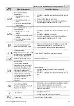
Page 142: ...compen sation Red uce tor que com pensa tion Suitable torque compensation No No No No No Ye s Yes Ye s Yes Yes Maybe AC motor drive has malfunction or error due to noise Please contact DELTA Can acce...

Page 143: ...tage to be within spec Has over voltage occurred without load Maybe AC motor drive has malfunction or misoperation due to noise Please contact DELTA Yes Yes Yes Yes Yes Yes No No No No No When OV occu...

Page 144: ...within specification Make necessary corrections such as change power supply system for requirement Check if there is heavy load with high start current in the same power system Check if Lv occurs whe...

Page 145: ...Change cooling fan Check if cooling fan is jammed Remove obstruction Check if surrounding temperature is within specification Adjust surrounding temperature to specification Maybe AC motor drive has...

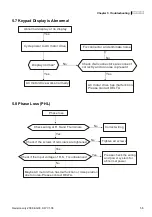
Page 146: ...ectors are connect correctly and no noise is present AC motor drive has malfunction Please contact DELTA 5 8 Phase Loss PHL Phase loss No No Yes Yes Check wiring at R S and T terminals Correct wiring...

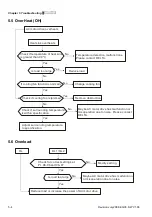
Page 147: ...ase contact DELTA Press UP key to set frequency Yes Modify frequency setting Check if input FWD or REV command Check if the wiring of FWD DCM and REV DCM is correct Yes Change switch or relay Set freq...

Page 148: ...finished with executing Pr 05 15 If the setting of Pr 05 00 to Pr 05 14 are the same Is it in PLC mode Press UP DOWN key to see if speed has any change If there is any change of the signal that sets f...

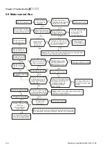
Page 149: ...ntact DELTA Increase torque compensation Check if the torque compensation is suitable Thicken or shorten the wiring between the motor and AC motor drive Reduce load or increase the capacity of AC moto...

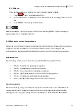
Page 150: ...and no receive 5 14 Environmental Condition Since the AC motor drive is an electronic device you should comply with the environmental conditions The following steps should also be followed 1 To preven...

Page 151: ...If phase lead capacitors are used never on the AC motor drive output use serial reactors to prevent capacitors damage from high harmonics serial reactor phase lead capacitor Motor Temperature Rises Wh...

Page 152: ...an abnormal increase in current IGBT protection Insulated Gate Bipolar Transistor 1 Check whether the motors horsepower corresponds to the AC drive output power 2 Check the wiring connections between...

Page 153: ...2 3 Increase the AC drive s output capacity i e bigger horsepower drive Internal electronic overload trip 1 Check for possible motor overload 2 Check electronic thermal overload setting 3 Increase mot...

Page 154: ...rnal terminal EF GND is closed the output will be turned off Under N O E F 2 Press RESET after fault has been cleared Emergency stop When the multi function input terminals MI1 to MI4 stop AC drive st...

Page 155: ...lt 150 300HP Remove any foreign objects on the heatsinks and check for possible dirty heat sink fins Fan 2 fault 150 300HP Remove any foreign objects on the heatsinks and check for possible dirty heat...

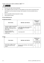
Page 156: ...condition and to ensure a long life It is recommended to have a qualified technician perform a check up of the AC motor drive regularly Daily Inspection Basic check up items to detect if there were an...

Page 157: ...ricity Periodical Maintenance Ambient environment Maintenance Period Check Items Methods and Criterion Daily Half Year One Year Check the ambient temperature humidity vibration and see if there are an...

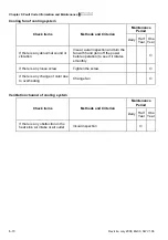
Page 158: ...ural inspection If there are any loose screws Tighten the screws If any part is deformed or damaged Visual inspection If there is any color change by overheating Visual inspection If there is any dust...

Page 159: ...DC capacity of main circuit Maintenance Period Check Items Methods and Criterion Daily Half Year One Year If there is any leakage of liquid change of color cracks or deformation Visual inspection Mea...

Page 160: ...One Year If there are any loose screws Visual and aural inspection Tighten screw if necessary If the contact works correctly Visual inspection Printed circuit board and connector of main circuit Main...

Page 161: ...tion Visual aural inspection and turn the fan with hand turn off the power before operation to see if it rotates smoothly If there is any loose screw Tighten the screw If there is any change of color...

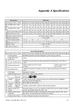
Page 162: ...Modulation carrier frequency 2 6kHz Output Frequency Resolution 0 01Hz Torque Characteristics Including the auto torque auto slip compensation starting torque can be 150 at 1 0Hz Overload Endurance 15...

Page 163: ...ier Frequency Protection Self testing Over Voltage Over Current Under Voltage Overload Overheating External Fault Electronic thermal Ground Fault Phase loss Cooling Methods Forced Fan cooled Installat...

Page 164: ...ed Brake Resistors Model No of Units Used Brake Torque 10 ED Minimum Equivalent Resistor Value for Each AC Drive 7 5 5 5 3 111 500W 100 BR500W100 1 125 60 10 7 5 4 148 1000W 75 BR1K0W075 1 125 45 15 1...

Page 165: ...ke unit thoroughly prior to installation and operation 8 In applications with brake resistor or brake unit Pr 06 00 Over voltage stall prevention must be disabled And Pr 08 18 AVR function shall not b...

Page 166: ...Thermal Overload Relay or temperature switch Surge Absorber Thermal Overload Relay Brake Resistor Brake Unit P N Note1 When using the AC drive with DC reactor please refer to wiring diagram in the AC...

Page 167: ...mes maximum output current rating Refer to Appendix A for rated input output current 3 phase Model Recommended non fuse breaker A VFD055F43B G 30 VFD075F43B G 40 VFD110F43A G 50 VFD150F43A G 60 VFD185...

Page 168: ...G 25 24 50 JJS 50 VFD150F43A G 32 32 60 JJS 60 VFD185F43A G 39 38 75 JJS 70 VFD220F43A G 49 45 100 JJS 100 VFD300F43A G 60 60 125 JJS 125 VFD370F43A G 63 73 150 JJS 150 VFD450F43A G 90 91 175 JJS 175...

Page 169: ...35 52 5 0 8 1 2 22 30 45 67 5 0 7 1 2 30 40 55 82 5 0 5 0 85 37 50 80 120 0 4 0 7 45 60 80 120 0 4 0 7 55 75 100 150 0 3 0 45 75 100 130 195 0 2 0 3 90 125 160 240 0 15 0 23 110 150 200 300 0 11 0 185...

Page 170: ...s Max continuous Amps 3 Impedance 5 Impedance 0 75 1 4 6 9 12 1 5 2 4 6 6 5 9 2 2 3 8 12 5 7 5 3 7 5 12 18 2 5 4 2 5 5 7 5 18 27 1 5 2 5 7 5 10 18 27 1 5 2 5 11 15 25 37 5 1 2 2 15 20 35 52 5 0 8 1 2...

Page 171: ...the capacitors may cause voltage dip The AC motor drive may be damaged when over current occurs during operation Correct wiring M1 M2 Mn reactor AC motor drive AC motor drive AC motor drive motor moto...

Page 172: ...ons etc The AC line reactor should be installed when the power supply capacity is 500kVA or more and exceeds 6 times the inverter capacity or the mains wiring distance 10m When the mains power capacit...

Page 173: ...table above gives approximate wire size for the zero phase reactors but the selection is ultimately governed by the type and diameter of cable fitted i e the cable must fit through the center hole of...

Page 174: ...e Left Key Move cursor to the left UP and DOWN Key Set the parameter number and changes the numerical data such as Master Frequency FWD REV Key Select FWD REV operation B 6 2 Explanation of Display Me...

Page 175: ...red in memory To modify an entry use the or keys Err displays if the input is invalid Communication Error Please check the AC motor drive user manual Chapter 4 Group 9 Communication Parameter for more...

Page 176: ...peed power and the change of load capacity The following table lists the factors you need to consider depending on your requirements Related Specification Item Speed and torque characteristics Time ra...

Page 177: ...capacity _ _ _ _ _ _ 1 cos 1 1 1 kVA drive motor AC of capacity rated the k n n P k n n N k s C s s T s T 2 2 The current should be less than the rated current of AC motor drive A Acceleration time 60...

Page 178: ...oltage V M I Motor rated current A for commercial power k Correction factor calculated from current distortion factor 1 05 1 1 depending on PWM method 1 C P Continuous motor capacity kVA PC1 KPMnT cos...

Page 179: ...r D O L Direct On Line a lower starting torque output with AC Motor Drive can be expected If higher starting torque is required such as for elevators mixers tooling machines etc use an AC Motor Drive...

Page 180: ...operate a standard 3 phase induction motor take the following precautions 1 The energy loss is greater than for an inverter duty motor 2 Avoid running motor at low speed for a long time Under this co...

Page 181: ...f a standard motor Please check before operation and select the capacity of the AC motor drive carefully When changing the pole number the motor needs to be stopped first If over current occurs during...

Page 182: ...at low speeds At high speeds of 50 60Hz and above lifetime reducing noises and vibrations may occur Motor torque The torque characteristics of a motor operated by an AC motor drive and commercial main...

Page 183: ...Appendix C How to Select the Right AC Motor Drive C 8 Revision July 2008 EG03 SW V1 06 This page intentionally left blank...

Reviews: