Installing System Components
131
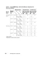
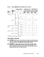
Table 3-3.
Sample UDIMM Memory Configurations (Per Processor)
Installing Memory Modules
WARNING:
Only trained service technicians are authorized to remove the system
cover and access any of the components inside the system. Before you begin this
procedure, review the safety instructions that came with the system.
WARNING:
The memory modules are hot to the touch for some time after the
system has been powered down. Allow time for the memory modules to cool
before handling them. Handle the memory modules by the card edges and avoid
touching the components on the memory module.
Memory
Mode
Memory
Module
Size
Memory Sockets
Single Processor
Dual Processor
1
4
7
2
5
8
3
6
9
Physical
Memory
(GB)
Available
Memory
(GB)
Physical
Memory
(GB)
Available
Memory
(GB)
Optimizer 1-GB
X
X
X
X
X
X
X
X
X
X
X
X
X
X
X X
1
2
3
4
6
all
2
4
6
8
12
all
2-GB
X
X
X
X
X
X
X
X
X
X
X
X
X
X
X X
2
4
6
8
12
all
4
8
12
16
24
all
Advanced
ECC
1
1-GB
vacant
X
X X
X
X X
2
4
all
4
8
all
2-GB
vacant
X
X X
X
X X
4
8
all
8
16
all
Mirroring 1-GB
vacant
X
X X
X
X X
2
4
1
2
4
8
2
4
2-GB
vacant
X
X X
X
X X
4
8
2
4
8
16
4
8
1
Requires x4- or x8-based memory modules
Summary of Contents for PowerVault NX3000
Page 1: ...Dell PowerVault NX3000 Systems Hardware Owner s Manual ...
Page 180: ...180 Jumpers and Connectors ...
Page 182: ...182 Getting Help ...
Page 192: ...192 Glossary ...
Page 200: ...200 Index ...


