


Diagnostic information
2-123
Printhead service check
CAUTION:
The printhead is not a serviceable FRU. Do not disassemble the printhead.
The printhead assembly does not contain any service replaceable parts or components. If service error code
930.xx displays, the wrong printhead is installed in the printer. See
“Printhead” on page 7-10
.
Note:
A 201.xx paper jam may also indicate a failing printhead. The paper may have jammed prior to or at the
input sensor. Print the event log and see if 201 or 931 errors are logged.
Signature button assembly service check
cartridge and the signature button contact assembly.
Service tip: An intermittent
32.xx-Unsupported Cartridge
User Error message can be caused by poor contact
between the signature button cartridge contacts in the upper front cover and the chip. Also check for proper
seating of the signature button cartridge cable to the system board.
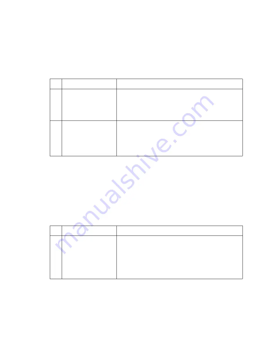
Service error code
Explanation
1
Error code 931.xx
No first HYSNC Signal
Error Code 932
Lost HYSNC
These errors usually indicate a failure in the HYSNC signal to the
printhead. Check the continuity of the cables connected to J2 and J4
on the system board. If incorrect, replace the defective cable. The
voltage at J4-1 measures approxi5 V dc. If incorrect, replace
the system board. The voltage at J2-7 measures approximately
+24 V dc. If incorrect, replace the system board. If correct, replace
the printhead assembly.
2
Error Code 934.xx
Mirror motor lost lock Error
Code 935
Mirror motor unable to
reach operating speed
These error codes indicate a problem with the mirror motor circuit in
the printhead assembly or the mirror motor cable to the system board
cable or system board assembly. The voltage at J5-2 measures
approxi24 V dc. If incorrect, replace the system board. If
correct, replace the FRUs in the following order:
• System board
• Printhead assembly
FRU
Action
1
Signature button contact
assembly
System board
Check the voltage on the signature button cartridge contact. The
voltage measures approxi3.8 V dc when not writing data to
the system board. If data is being written, the voltage measures
approximately 0 V dc. If incorrect, disconnect the cable from J19 on
the system board, and check the voltage on J19-1. The voltage
measures approxi5 V dc.
• If incorrect, replace the system board.
• If correct, replace the signature button cartridge contact
assembly.
Note:
If you are unable to clear a
32.xx-Unsupported Cartridge
User Error message, be sure a Dell 5210n/
5310n print cartridge is correctly installed in the printer. The cartridge is easily identified by the contact board on
the right side rear of the cartridge. Install another print cartridge before attempting to troubleshoot the printer.
Make sure the signature button cable is properly connected to J14 on the system board. Check the print cartridge
for damage or improper installation of the chip. Also, be sure there is proper contact between the chip on the
Summary of Contents for 5210n Mono Laser Printer
Page 1: ...Dell 5210n 5310n Service Manual 14Jan2010 ...
Page 15: ...Laser notices xv Japanese Laser Notice ...
Page 16: ...xvi Service Manual Korean Laser Notice ...
Page 42: ...1 22 Service Manual ...
Page 172: ...2 130 Service Manual ...
Page 222: ...3 50 Service Manual ...
Page 316: ...5 14 Service Manual ...
Page 318: ...6 2 Service Manual ...
Page 320: ...7 2 Service Manual Assembly 1 Covers 7 9 8 14 12 15 13 16 17 3 3 2 5 1 4 4 5 6 6 10 11 ...
Page 322: ...7 4 Service Manual Assembly 2 Frame 1 1 5 1 1 2 3 4 6 3 7 8 9 ...
Page 324: ...7 6 Service Manual Assembly 3 Frame 2 3 10 6 12 17 15 8 14 2 9 5 16 4 11 7 13 18 1 19 20 ...
Page 328: ...7 10 Service Manual Assembly 5 Printhead 1 2 2 3 ...
Page 330: ...7 12 Service Manual Assembly 6 Paper feed autocompensator 5 3 4 6 2 1 7 1 6 ...
Page 332: ...7 14 Service Manual Assembly 7 Paper feed multipurpose feeder 3 5 2 4 1 1 5 ...
Page 334: ...7 16 Service Manual Assembly 8 Paper feed alignment 3 2 1 4 ...
Page 336: ...7 18 Service Manual Assembly 9 Integrated 250 sheet paper tray 3 7 5 2 6 4 1 ...
Page 338: ...7 20 Service Manual Assembly 10 Integrated 500 sheet paper tray 1 3 7 5 4 6 2 ...
Page 340: ...7 22 Service Manual Assembly 11 Drives Main drive and developer drive 3 2 4 1 7 6 5 ...
Page 344: ...7 26 Service Manual Assembly 13 Transfer charging 3 2 4 1 6 5 7 9 8 ...
Page 346: ...7 28 Service Manual Assembly 14 Electronics power supplies 3 5 2 4 1 ...
Page 348: ...7 30 Service Manual Assembly 15 Electronics card assemblies Note 1 2 3 4 5 5 ...
Page 350: ...7 32 Service Manual Assembly 16 Electronics shields 5 6 2 1 3 4 7 2 4 2 2 2 2 ...
Page 354: ...7 36 Service Manual Assembly 19 Cabling diagrams 3 3 5 2 4 1 ...
Page 356: ...7 38 Service Manual Assembly 20 Cabling diagrams 4 3 4 2 1 ...
Page 358: ...7 40 Service Manual Assembly 21 Cabling diagrams 5 1 2 3 3 3 4 5 ...
Page 370: ...7 52 Service Manual Assembly 32 High capacity output expander 3 1 ...
Page 372: ...7 54 Service Manual Assembly 33 5 bin mailbox 1 3 11 7 13 5 16 9 15 2 6 4 12 8 14 10 1 5 ...
Page 374: ...7 56 Service Manual Assembly 34 5 bin mailbox 2 2 1 ...
Page 376: ...7 58 Service Manual Assembly 35 High capacity feeder 1 2 5 3 6 7 8 1 4 9 10 ...
Page 378: ...7 60 Service Manual Assembly 36 High capacity feeder 2 3 1 2 4 ...
Page 388: ...7 70 Service Manual ...
Page 416: ...I 8 Service Manual ...