


Diagnostic information
2-93
Fuser narrow media sensor service check
If any of the following error codes are displayed, a problem may exist in the area of the narrow media sensor
assembly: 201.04, 201.14, 201.24, 201.34, 201.44, 201.54, and 201.94.
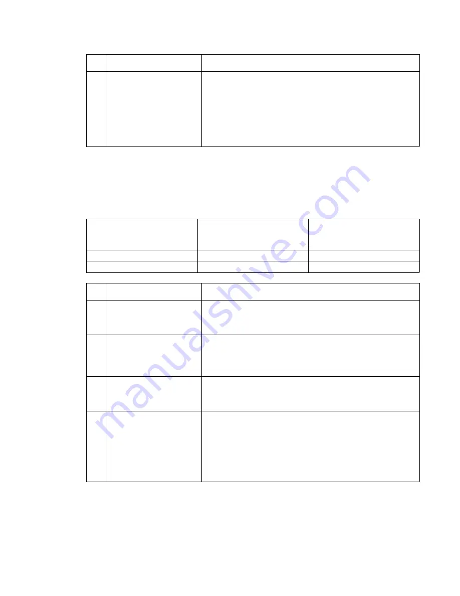
Fuser exit and fuser narrow media sensor status check
5
With the redrive assembly removed from the printer, enter the
Diagnostics mode and run the print test from tray 1 (for example,
select
PRINT TESTS
,
Tray 1
, and
Continuous
) and observe the
media as it passes over the exit and narrow media sensors. Check
that the sensor flags are operating correctly. If the sensor flags and
hardware are operating incorrectly, repair or replace the failing
sensor assembly. If no problem is found, check the fuser for any
signs of media in the fuser or any signs of toner or other
contamination. If a problem is found, clean or remove the debris or
contamination.
Printer not printing— no media
over sensors
Printer printing—media over
sensor(s), non-narrow media fed
through the printer
Printer printing—narrow media
fed through the printer
Exit sensor open
Exit sensor closed
Exit sensor closed
Narrow media sensor open
Narrow media sensor closed
Narrow media sensor open
FRU
Action
1
Fuser narrow media sensor
(sensor test)
Enter the Diagnostics mode, select
BASE SENSOR TEST
, and
select the
NM Sensor
to test it for proper operation. If the narrow
media sensor fails the test, go to step 2; if the narrow media sensor
does not pass the test, go to step 5.
2
Fuser narrow media sensor
cable
Check the fuser narrow media sensor cable for correct installation or
any signs of damage to the cable or to the connectors. If no problem
is found, go to step 3;. If a problem with the installation is found,
install the cable correctly. If damage to the cable or the connectors is
found, replace the cable.
3
Fuser narrow media sensor
flag
Make sure the sensor flag is not binding and is operating properly. If
the sensor is operating properly, go to step 4. If the sensor is not
operation properly, repair or replace the sensor assembly. See
“Fuser narrow media sensor removal” on page 4-35
.
4
Fuser assembly
Fuser narrow media sensor
cable
Fuser board
Fuser to system board
cable
System board
Check the continuity of the fuser narrow media sensor cable. If
incorrect, replace the cable; if correct, check the continuity of the
fuser to system board cable. If incorrect, replace the cable; if correct,
replace the following FRUs in the order shown:
• Fuser board
• Fuser assembly. See
“Fuser assembly removal” on page 4-27
.
• System board. See
“System board and inner shield removal”
on page 4-77
.
FRU
Action
Summary of Contents for 5210n Mono Laser Printer
Page 1: ...Dell 5210n 5310n Service Manual 14Jan2010 ...
Page 15: ...Laser notices xv Japanese Laser Notice ...
Page 16: ...xvi Service Manual Korean Laser Notice ...
Page 42: ...1 22 Service Manual ...
Page 172: ...2 130 Service Manual ...
Page 222: ...3 50 Service Manual ...
Page 316: ...5 14 Service Manual ...
Page 318: ...6 2 Service Manual ...
Page 320: ...7 2 Service Manual Assembly 1 Covers 7 9 8 14 12 15 13 16 17 3 3 2 5 1 4 4 5 6 6 10 11 ...
Page 322: ...7 4 Service Manual Assembly 2 Frame 1 1 5 1 1 2 3 4 6 3 7 8 9 ...
Page 324: ...7 6 Service Manual Assembly 3 Frame 2 3 10 6 12 17 15 8 14 2 9 5 16 4 11 7 13 18 1 19 20 ...
Page 328: ...7 10 Service Manual Assembly 5 Printhead 1 2 2 3 ...
Page 330: ...7 12 Service Manual Assembly 6 Paper feed autocompensator 5 3 4 6 2 1 7 1 6 ...
Page 332: ...7 14 Service Manual Assembly 7 Paper feed multipurpose feeder 3 5 2 4 1 1 5 ...
Page 334: ...7 16 Service Manual Assembly 8 Paper feed alignment 3 2 1 4 ...
Page 336: ...7 18 Service Manual Assembly 9 Integrated 250 sheet paper tray 3 7 5 2 6 4 1 ...
Page 338: ...7 20 Service Manual Assembly 10 Integrated 500 sheet paper tray 1 3 7 5 4 6 2 ...
Page 340: ...7 22 Service Manual Assembly 11 Drives Main drive and developer drive 3 2 4 1 7 6 5 ...
Page 344: ...7 26 Service Manual Assembly 13 Transfer charging 3 2 4 1 6 5 7 9 8 ...
Page 346: ...7 28 Service Manual Assembly 14 Electronics power supplies 3 5 2 4 1 ...
Page 348: ...7 30 Service Manual Assembly 15 Electronics card assemblies Note 1 2 3 4 5 5 ...
Page 350: ...7 32 Service Manual Assembly 16 Electronics shields 5 6 2 1 3 4 7 2 4 2 2 2 2 ...
Page 354: ...7 36 Service Manual Assembly 19 Cabling diagrams 3 3 5 2 4 1 ...
Page 356: ...7 38 Service Manual Assembly 20 Cabling diagrams 4 3 4 2 1 ...
Page 358: ...7 40 Service Manual Assembly 21 Cabling diagrams 5 1 2 3 3 3 4 5 ...
Page 370: ...7 52 Service Manual Assembly 32 High capacity output expander 3 1 ...
Page 372: ...7 54 Service Manual Assembly 33 5 bin mailbox 1 3 11 7 13 5 16 9 15 2 6 4 12 8 14 10 1 5 ...
Page 374: ...7 56 Service Manual Assembly 34 5 bin mailbox 2 2 1 ...
Page 376: ...7 58 Service Manual Assembly 35 High capacity feeder 1 2 5 3 6 7 8 1 4 9 10 ...
Page 378: ...7 60 Service Manual Assembly 36 High capacity feeder 2 3 1 2 4 ...
Page 388: ...7 70 Service Manual ...
Page 416: ...I 8 Service Manual ...


