4.8
Left Position Guide Rail Plate Installation . . . . . . . . . . . . . . . . . . . . . . . .
4–11
4.9
Right Position Guide Rail Plate Installation . . . . . . . . . . . . . . . . . . . . . . .
4–13
4.10
Preparing the SA7X Enclosure . . . . . . . . . . . . . . . . . . . . . . . . . . . . . . . . . .
4–14
4.11
Installing the SA7X Enclosure . . . . . . . . . . . . . . . . . . . . . . . . . . . . . . . . . .
4–15
4.11.1
Completing the Installation . . . . . . . . . . . . . . . . . . . . . . . . . . . . . . . . .
4–19
5 Troubleshooting the SA7x
5.1
Identifying Problems . . . . . . . . . . . . . . . . . . . . . . . . . . . . . . . . . . . . . . . . .
5–1
5.2
Troubleshooting a Dead Enclosure . . . . . . . . . . . . . . . . . . . . . . . . . . . . . . .
5–1
5.2.1
If the Fault Indicator Is Lit . . . . . . . . . . . . . . . . . . . . . . . . . . . . . . . . .
5–1
5.2.2
If the Fault Indicator Is Not Lit . . . . . . . . . . . . . . . . . . . . . . . . . . . . . .
5–2
5.3
Troubleshooting a Flashing Drive Power Indicator . . . . . . . . . . . . . . . . . .
5–3
5.4
Troubleshooting Excessive Drive Errors or a Fault Condition . . . . . . . . . .
5–5
5.5
Reading OCP Error Codes . . . . . . . . . . . . . . . . . . . . . . . . . . . . . . . . . . . . .
5–5
5.6
Troubleshooting a Drive Not Visible to the Controller . . . . . . . . . . . . . . . .
5–6
5.7
Troubleshooting the OCP . . . . . . . . . . . . . . . . . . . . . . . . . . . . . . . . . . . . . .
5–6
A Environmental Stabilization
B RA7x Error Rates
B.1
RA7x Error Rates . . . . . . . . . . . . . . . . . . . . . . . . . . . . . . . . . . . . . . . . . . . .
B–1
C Revision Support
Index
Figures
1–1
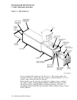
SA7x Enclosure . . . . . . . . . . . . . . . . . . . . . . . . . . . . . . . . . . . . . . . . . .
1–2
1–2
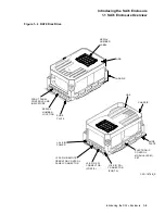
RA70 Disk Drive . . . . . . . . . . . . . . . . . . . . . . . . . . . . . . . . . . . . . . . . .
1–3
1–3
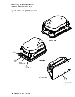
RA71 Through RA73 Disk Drives . . . . . . . . . . . . . . . . . . . . . . . . . . . .
1–4
1–4
Using the ESD Grounding Strap . . . . . . . . . . . . . . . . . . . . . . . . . . . . .
1–12
2–1
SA7x Enclosure Front Panel . . . . . . . . . . . . . . . . . . . . . . . . . . . . . . . .
2–2
2–2
SA7x Enclosure Rear Panel . . . . . . . . . . . . . . . . . . . . . . . . . . . . . . . . .
2–6
3–1
SA70 Enclosure . . . . . . . . . . . . . . . . . . . . . . . . . . . . . . . . . . . . . . . . . .
3–3
3–2
RA7x Disk Drive Serial Number Location . . . . . . . . . . . . . . . . . . . . . .
3–4
3–3
Reversing the RA7x Shoe Plate . . . . . . . . . . . . . . . . . . . . . . . . . . . . . .
3–5
3–4
Replacing RA70 Disk Drive . . . . . . . . . . . . . . . . . . . . . . . . . . . . . . . . .
3–7
4–1
SA7x Enclosure Front Panel . . . . . . . . . . . . . . . . . . . . . . . . . . . . . . . .
4–4
4–2
Storage Device Add-On Sequence for the SA900 Storage Array (Front
View) . . . . . . . . . . . . . . . . . . . . . . . . . . . . . . . . . . . . . . . . . . . . . . . . . .
4–7
4–3
SA7x Front Clamping Assembly . . . . . . . . . . . . . . . . . . . . . . . . . . . . .
4–8
4–4
SA900 and SA7x Chassis Retaining Brackets . . . . . . . . . . . . . . . . . . .
4–9
4–5
SA7x Enclosure Guide Rail Assembly Installation . . . . . . . . . . . . . . . .
4–10
4–6
SA900 Mounting Rail Holes . . . . . . . . . . . . . . . . . . . . . . . . . . . . . . . . .
4–12
4–7
Installing the SA7x Enclosure in the SA900 . . . . . . . . . . . . . . . . . . . .
4–16
4–8
SA900 SDI Cable Connections . . . . . . . . . . . . . . . . . . . . . . . . . . . . . . .
4–18
iv

