2
Operating the SA7x
This chapter describes the SA7x enclosure’s front and rear panel switches and
indicators and explains how to use them. It also explains how to apply power to
the enclosure and how to place drives on line and off line.
Note
You must be a qualified Digital Multivendor Customer Services engineer
to perform procedures that involve the drive power switches or internal
storage array cabinet switches and indicators.
2.1 SA7x Switches and Indicators
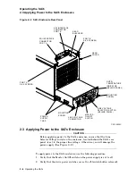
The SA7x switches and indicators are located on both the front and rear panels.
The front panel contains the operator control panel (OCP) and the drive dc
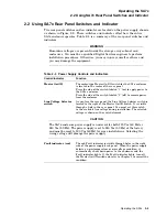
power switches. The rear panel contains the power supply related switches and
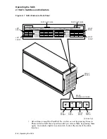
indicators. Figure 2–1 shows the SA7x enclosure front panel. The OCP is located
along the top enclosure and contains the Unit Select switch and four identical
sets of switches and indicators. Each set of switches and indicators is dedicated
to one of the four disk drive positions in the enclosure. Drive power switches and
indicators for the four disk drive positions are located at the bottom.
Note
The switch and indicator set for each disk drive position is operational
ONLY when the disk drive is powered up.
2.1.1 Using the Switches and Indicators
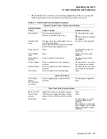
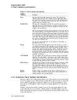
Table 2–1 is a summary of SA7x control and indicator functions. Table 2–2 is a
detailed description of OCP control and indicator functions. The following general
comments are also applicable:
• During power-on and spin-up of a drive, the OCP switches and indicators
have slightly modified meanings, as described in Section 2.4.1.
• The control set for each disk drive position contains Ready and Unit Number
indicators and switches for run operation, fault conditions, write protection,
unit number selection, and A/B port selection.
Operating the SA7x 2–1

