unit; double clicking on the unit also takes you to the Unit view. When off - l i n e , You can delete
the unit by selecting
D e l e t e
f rom the Device Menu. Selecting
P ro p e rt i e s
f rom the Device
menu allows you to view and edit some of the device properties like the device's name, its
MAC address, Its Node address, and its peak output level. From the
P ro p e rt i e s
selection, you
can also see the firm w a re or OS (Operating System) version that the device has loaded
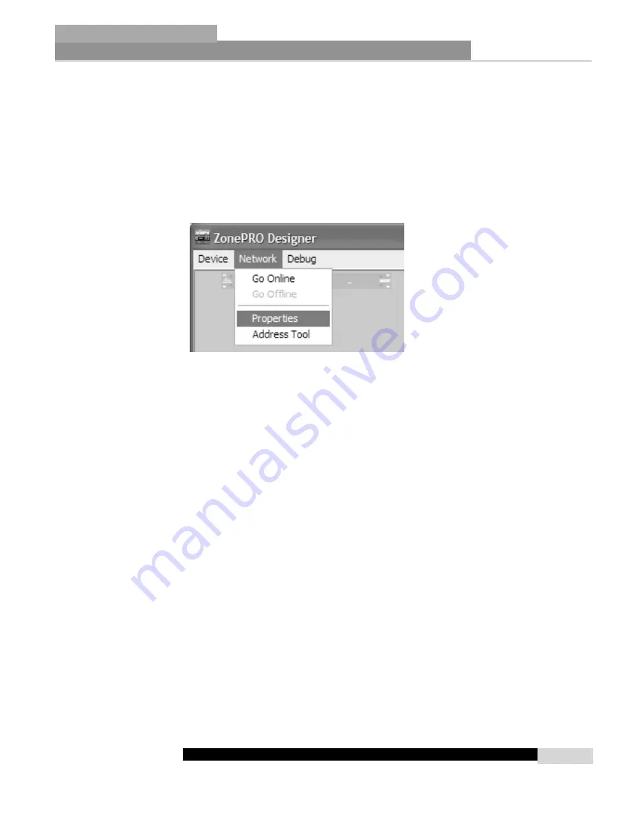
2.3.2 Network Menu
The Network Menu provides access to network parameters. If the computer cannot connect to
the ZonePro device you can select
Properties
from the Network Menu and check the COM
port assignment to make sure that you are connecting to the correct COM port. The Network
Menu also provides an
Address Tool
that can be used to discover other devices on the network
and resolve any address conflicts that may arise between units.
Note: Nodes
Any device that is on the network is considered a node and must be given a node address; this
is just usually a simple one or two digit number. Once you place the first device on the net-
work the GUI will assist you as you add further devices by adding 1 to the previous node
address as you add devices. For example, if the first device on the network is node address 1,
the second will be 2, and the third 3, unless you specifically change the node address with the
Network Address Tool. If the computer cannot connect to the ZonePRO device, check the COM
port assignment under Network Properties in the Venue View, and make sure that you are con-
necting to the correct COM port.
Note: Setting up a basic Network
The enclosed crossover Ethernet cable is used to connect a computer directly to a ZonePRO
1260/1261 without a hub or a switch. If you are using a hub or a switch, you must provide
your own cabling.
Since this cable is a crossover cable, it can not be used to wire Zone
Controllers or link to multiple ZonePRO units together using the Input Link Bus.
The factory default IP settings for the ZonePRO are as follows:
IP Address:
169.254.2.2
Subnet Mask:
255.255.0.0
Default Gateway:
0.0.0.0
These default settings are used for a simplified configuration when using Microsoft Window's
Automatic IP assignment. When Windows is configured to automatically obtain its IP settings
it will fall back to a network configuration that is compatible with the ZonePRO 1260 / 1261 if
the computer is on a network without a DHCP/BOOTP server. Using the enclosed crossover
cable is an example of such a network and is the recommended method of configuring a new
unit. Please keep in mind that it takes MS Windows 1-2 minutes after the cable is attached and
the ZonePRO is powered on for it to have its network settings compatible with the ZonePRO.
Because of this, do not start the ZonePRO Designer software for about 2 minutes after the cables
have been attached. For more information on how to properly configure the network setting
please refer to the appendix.
Software Overview
Section 2
ZonePRO
™
7
ZonePRO
™
User Manual
Summary of Contents for Zone Pro 1260
Page 1: ...User Manual 1260 1261 ...
Page 5: ...INTRO CUSTOMER SERVICE INFO Defining the ZonePRO WARRANTY INFO INTRODUCTION ZonePRO ...
Page 9: ...Getting Started Section 1 ZonePRO ...
Page 13: ...SOFTWARE OVERVIEW Section 2 ZonePRO ...
Page 19: ...SOFTWARE OPERATION Setup Section 3 ZonePRO ...
Page 27: ...DETAILED PARAMETERS Detailed Parameters Section 4 ZonePRO ...
Page 43: ...APPLICATION GUIDE Section 5 ZonePRO ...
Page 44: ...Application Guide 36 SECTION 5 ZonePRO ZonePRO User Manual 5 1 Restaurant Install ...
Page 46: ...Application Guide 38 SECTION 5 ZonePRO ZonePRO User Manual 5 2 Health Club Install ...
Page 48: ...Application Guide ZonePRO User Manual 40 Section 5 ZonePRO 5 3 Night Club Install ...
Page 50: ...Application Guide ZonePRO User Manual 42 Section 5 ZonePRO This page intentionally left blank ...
Page 51: ...APPLICATION Notes Section 6 ZonePRO ...
Page 56: ...Applications Notes 48 SECTION 6 ZonePRO ZonePRO User Manual ...
Page 57: ...Appendix ZonePRO ...
Page 60: ...ZonePRO User Manual 52 Appendix ZonePRO A 3 Block Diagram ...
Page 63: ...Appendix ZonePRO ZonePRO User Manual 55 Diagram A Diagram B Diagram C ...
Page 64: ...ZonePRO User Manual 56 Appendix ZonePRO Diagram A Diagram B Diagram C ...


