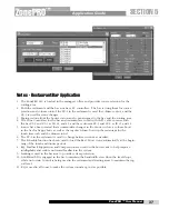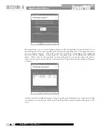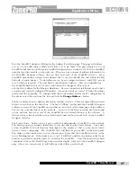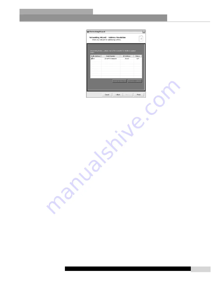
Now the ZonePRO designer will display the Address Resolution page. This page will inform
you as to any addressing conflicts and allow you to fix them. This page displays a list of
ZonePRO units that are on the main ZonePRO Designer device window as well as the ZonePRO
units that are discoverable on the network. There are four columns of address information for
the ZonePRO Designer software (the top line) and each of the ZonePRO devices.
Every
ZonePRO unit needs a unique Node Address that is used to identify the unit within the HQ
Network of audio devices. Node Addresses can be any integer between 1 and 65534 except
for 48 which is reserved. The next field is the Hardware Address. This is an identifier for
the ZonePRO hardware it is a fix value and can not be changed. This value is
also the MAC address for the Ethernet Hardware. Devices connected via Ethernet need to have
a unique and correctly configured IP address. For more details on correct IP Network settings
please read the appendix. To change either the Node address and/or the IP configuration of
the device select the unit from the list and click the
Change Address...
button.
The Last column of in the Address Resolution window is Status. There are three different states
that are shown here in the status box. The first is Offline. In this state the ZonePRO Designer
software is aware of the ZonePRO unit and has an icon for it on the main page of the software
but can not currently find it on the network. A device in the Detected state has been found
on the network but not as one of the ZonePRO devices already known to the software.
A
devices status is Resolved when it has both been found on the network and in the ZonePRO
Designer software.
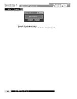
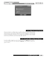
The Locate Node... button can be a very useful tool help identify a ZonePRO on the network.
This button pops up a window that allows you to start and stop the locate feature. Once start-
ed the ZonePRO 1260 will flash the back-light on the display so that you can know which
device you are configuring. The ZonePRO 1261 will flash its power LED on the front panel.
The slider on this window lets you set the amount of time that the ZonePRO will stay in the
locate (flashing) mode. If the slider is set to “inf.” it will flash until the stop button in the locate
window is pressed or until the power is cycled on the ZonePRO.
Once this function has been
completed, click on the Finish Page button and the display will you to the ZonePRO designer
page, where you can proceed to add/edit any units within your network.
Application Notes
SECTION 6
ZonePRO
™
47
ZonePRO™ User Manual
Summary of Contents for Zone Pro 1260
Page 1: ...User Manual 1260 1261 ...
Page 5: ...INTRO CUSTOMER SERVICE INFO Defining the ZonePRO WARRANTY INFO INTRODUCTION ZonePRO ...
Page 9: ...Getting Started Section 1 ZonePRO ...
Page 13: ...SOFTWARE OVERVIEW Section 2 ZonePRO ...
Page 19: ...SOFTWARE OPERATION Setup Section 3 ZonePRO ...
Page 27: ...DETAILED PARAMETERS Detailed Parameters Section 4 ZonePRO ...
Page 43: ...APPLICATION GUIDE Section 5 ZonePRO ...
Page 44: ...Application Guide 36 SECTION 5 ZonePRO ZonePRO User Manual 5 1 Restaurant Install ...
Page 46: ...Application Guide 38 SECTION 5 ZonePRO ZonePRO User Manual 5 2 Health Club Install ...
Page 48: ...Application Guide ZonePRO User Manual 40 Section 5 ZonePRO 5 3 Night Club Install ...
Page 50: ...Application Guide ZonePRO User Manual 42 Section 5 ZonePRO This page intentionally left blank ...
Page 51: ...APPLICATION Notes Section 6 ZonePRO ...
Page 56: ...Applications Notes 48 SECTION 6 ZonePRO ZonePRO User Manual ...
Page 57: ...Appendix ZonePRO ...
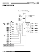
Page 60: ...ZonePRO User Manual 52 Appendix ZonePRO A 3 Block Diagram ...
Page 63: ...Appendix ZonePRO ZonePRO User Manual 55 Diagram A Diagram B Diagram C ...
Page 64: ...ZonePRO User Manual 56 Appendix ZonePRO Diagram A Diagram B Diagram C ...

