PCM-3362 User Manual
58
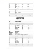
8
N/C
9
LVDS0_z_D1-
OUT
LVDS
10
N/C
11
LVD
OUT
LVDS
12
N/C
13
LVDS0_z_D2-
OUT
LVDS
14
N/C
15
LVDS OUT
LVDS
16
N/C
17
LVDS0_z_CLK- OUT
LVDS
18
N/C
19
+V_LCD
PWR
+5 V/+3.3 V
20
+V_LCD
PWR
+5 V/+3.3 V
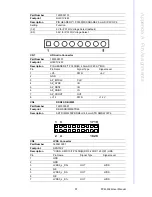
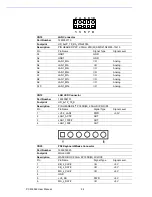
CN7
Internal LCD Backlight
Part Number
1655305020
Footprint
WHL5V-2M
Description
WAFER BOX 2.0mm 5P 180D(M) W/LOCK
Pin
Pin Name
Signal Type
Signal Level
1
+V12_INVERTER
PWR
+12V
2
GND
GND
3
LVDS0_ENABKL
OUT
+3.3V
4
LVDS0_VBR
OUT
+3.3V
5
+V5_INVERTER
PWR
+5V
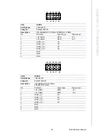
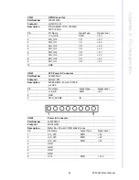
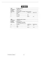
CN8
VGA Connector
Part Number
1655912120
Footprint
WB12P-S1.25mm
Description
Wafer Box 1.25mm 12P 90D(M) SMD 85204-12001
Pin
Pin Name
Signal Type
Signal Level
1
GND
GND
2
VGA_z_R
OUT
+5 V
3
VGA_z_G
OUT
+5 V
4
VGA_z_B
OUT
+5 V
5
GND
GND
6
+V5_CRT
PWR
+5 V
7
VGA_z_DDAT
OUT
+5 V
8
VGA_z_DCLK
OUT
+5 V
9
GND
GND
10
VGA_z_HS
OUT
+5 V
11
VGA_z_VS
OUT
+5 V
12
GND
GND
5
1
Summary of Contents for PCM-3362
Page 1: ...Data Modul AG www data modul com Specification PCM 3362 ...
Page 13: ...PCM 3362 User Manual 6 ...
Page 14: ...Chapter 2 2 Hardware Installation ...
Page 23: ...PCM 3362 User Manual 16 ...
Page 24: ...Chapter 3 3 AMI BIOS Setup ...
Page 44: ...Chapter 4 4 Software Introduction Installation ...
Page 55: ...PCM 3362 User Manual 48 ...
Page 56: ...Chapter 5 5 Chipset Software Installation Utility ...
Page 58: ...Chapter 6 6 Integrated Graphic Device Setup ...
Page 60: ...Chapter 7 7 LAN Configuration ...
Page 75: ...PCM 3362 User Manual 68 ...
Page 76: ...Appendix C C Mechanical Drawings ...
Page 81: ...PCM 3362 User Manual 74 ...
Page 82: ...Appendix D D Watchdog Timer and GPIO sample code ...

