


PCM-3362 User Manual
12
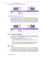
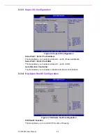
2.4.3
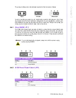
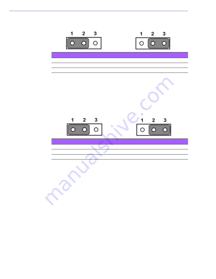
COM3 RS422/RS485 Select (JP3)
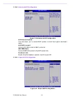
2.4.4
PCI I/O Voltage Select (JP4)
The PCI Host board will always determine the PCI signaling level on the bus by set-
ting all VI/O pins to either 3.3 V or 5 V. If VI/0 is set to 3.3 V, then the system will use
3.3 V I/O signaling, likewise, if VI/O is set to 5 V, then the system will use 5 V I/O sig-
naling. Some PCI host modules may only allow one of the options, while others may
provide a jumper to allow the user to select the signaling level. Once the signaling
level is selected, the remaining boards in the system must use that signaling level.
2.5
Installing SODIMMs
The procedures for installing SODIMMs are described below. Please follow these
steps carefully. You can install SDRAM memory modules using 200-pin SODIMMs
(Small Outline Dual In-line Memory Modules).
1.
Ensure that all power supplies to the system are switched off.
2.
Tilt the SODIMM card just above the board and slide it into the housing card
slot.
3.
Push the module into the socket until the module gently snaps in. There should
only be a slight insertion force to engage the module into the contacts. Make
sure that the module and the housing are aligned and locked in place.
2.6
Flash
The board provides onboard NAND Flash memory to replace CF socket. NANDriv-
e
TM
integrated circuits (IC) are high-performance, fully-integrated, embedded flash
solid state drives. They combine an integrated ATA Controller in a multi-chip pack-
age. These products are ideal for industrial grade solid state mass storage applica-
tions offering new and expanded functionality while enabling cost effective designs.
Table 2.5: COM3 RS422/RS485 Select (JP3)
Setting
Function
1-2
RS-485 (default)
2-3
RS-422
Table 2.6: PCI I/O Voltage Select (JP4)
Setting
Function
1-2
5 V (default)
2-3
3.3 V
Summary of Contents for PCM-3362
Page 1: ...Data Modul AG www data modul com Specification PCM 3362 ...
Page 13: ...PCM 3362 User Manual 6 ...
Page 14: ...Chapter 2 2 Hardware Installation ...
Page 23: ...PCM 3362 User Manual 16 ...
Page 24: ...Chapter 3 3 AMI BIOS Setup ...
Page 44: ...Chapter 4 4 Software Introduction Installation ...
Page 55: ...PCM 3362 User Manual 48 ...
Page 56: ...Chapter 5 5 Chipset Software Installation Utility ...
Page 58: ...Chapter 6 6 Integrated Graphic Device Setup ...
Page 60: ...Chapter 7 7 LAN Configuration ...
Page 75: ...PCM 3362 User Manual 68 ...
Page 76: ...Appendix C C Mechanical Drawings ...
Page 81: ...PCM 3362 User Manual 74 ...
Page 82: ...Appendix D D Watchdog Timer and GPIO sample code ...


