PCM-3362 User Manual
66
B.1
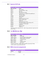
System I/O Ports
* PNP audio I/O map range from 220 ~ 250H (16 bytes) MPU-401 select from 300 ~
330H (2 bytes)
B.2
1st MB Memory Map
* If Ethernet boot ROM is disabled (Ethernet ROM occupies about 16 KB)
* E0000 - EFFFF is reserved for BIOS POST
B.3
DMA channel assignments
Table B.1: System I/O ports
Addr. range (Hex)
Device
000-01F
DMA controller
020-021
Interrupt controller 1, master
040-05F
8254 timer
060-06F
8042 (keyboard controller)
070-071
Real-time clock, non-maskable interrupt (NMI) mask
87-8A
DMA page register
0A0-0A1
Interrupt controller 2
0C0-0DF
DMA controller
1F0-1F8
Fixed disk
278-27F
Reserved (Parallel port 2,LTP3)
2E8-2EF
Reserved (Series port 4)
2F8-2FF
Serial port 2
378-37F
Parallel printer port 1 (LPT 2)
3B0-3BF
Monochrome display and printer adapter (LPT1)
3D0-3DF
Color/graphics monitor adapter
3E8-3EF
Series port 3
3F0-3F7
Diskette controller
3F8-3FF
Serial port 1
Table B.2: 1st MB memory map
Addr. range (Hex)
Device
F0000h - FFFFFh
System ROM
*CC000h - EFFFFh
Unused (reserved for Ethernet ROM)
C0000h - CBFFFh
Expansion ROM (for VGA BIOS)
B8000h - BFFFFh
CGA/EGA/VGA text
B0000h - B7FFFh
Unused
A0000h - AFFFFh
EGA/VGA graphics
00000h - 9FFFFh
Base memory
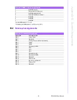
Table B.3: DMA channel assignments
Channel
Function
0
Available
Summary of Contents for PCM-3362
Page 1: ...Data Modul AG www data modul com Specification PCM 3362 ...
Page 13: ...PCM 3362 User Manual 6 ...
Page 14: ...Chapter 2 2 Hardware Installation ...
Page 23: ...PCM 3362 User Manual 16 ...
Page 24: ...Chapter 3 3 AMI BIOS Setup ...
Page 44: ...Chapter 4 4 Software Introduction Installation ...
Page 55: ...PCM 3362 User Manual 48 ...
Page 56: ...Chapter 5 5 Chipset Software Installation Utility ...
Page 58: ...Chapter 6 6 Integrated Graphic Device Setup ...
Page 60: ...Chapter 7 7 LAN Configuration ...
Page 75: ...PCM 3362 User Manual 68 ...
Page 76: ...Appendix C C Mechanical Drawings ...
Page 81: ...PCM 3362 User Manual 74 ...
Page 82: ...Appendix D D Watchdog Timer and GPIO sample code ...

