
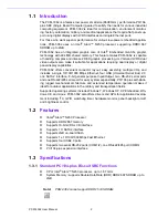


11
PCM-3362 User Manual
Chapter 2
H
ardware
Installation
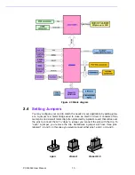
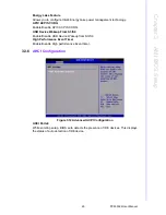
The jumper settings are schematically depicted in this manual as follows:
A pair of needle-nose pliers may be helpful when working with jumpers. If you have
any doubts about the best hardware configuration for your application, contact your
local distributor or sales representative before you make any changes. Generally, you
simply need a standard cable to make most connections.
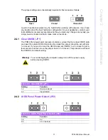
2.4.1
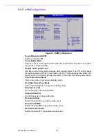
Clear CMOS (JP1)
The PCM-3362 single board computer contains a jumper that can erase CMOS data
and reset the system BIOS information. Normally this jumper should be set with pins
1-2 closed. If you want to reset the CMOS data, set CMOS1 to 2-3 closed for just a
few seconds, and then move the jumper back to 1-2 closed. This procedure will reset
the CMOS to its default setting.
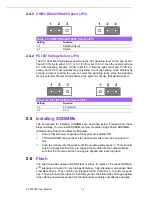
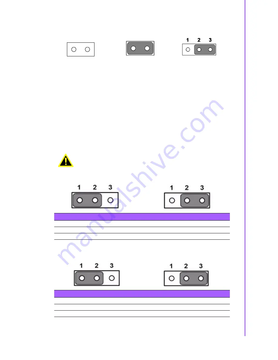
2.4.2
LVDS Panel Power Select (JP2)
Open
Closed
Closed 2-3
Warning!
To avoid damaging the computer, always turn off the power supply
before clearing CMOS.
Table 2.3: Clear CMOS (JP1)
Setting
Function
1-2
Normal (default)
2-3
Clear CMOS
Table 2.4: LVDS Panel Power Select (JP2)
Setting
Function
1-2
5 V
2-3
3.3 V (default)
Summary of Contents for PCM-3362
Page 1: ...Data Modul AG www data modul com Specification PCM 3362 ...
Page 13: ...PCM 3362 User Manual 6 ...
Page 14: ...Chapter 2 2 Hardware Installation ...
Page 23: ...PCM 3362 User Manual 16 ...
Page 24: ...Chapter 3 3 AMI BIOS Setup ...
Page 44: ...Chapter 4 4 Software Introduction Installation ...
Page 55: ...PCM 3362 User Manual 48 ...
Page 56: ...Chapter 5 5 Chipset Software Installation Utility ...
Page 58: ...Chapter 6 6 Integrated Graphic Device Setup ...
Page 60: ...Chapter 7 7 LAN Configuration ...
Page 75: ...PCM 3362 User Manual 68 ...
Page 76: ...Appendix C C Mechanical Drawings ...
Page 81: ...PCM 3362 User Manual 74 ...
Page 82: ...Appendix D D Watchdog Timer and GPIO sample code ...


