63
PCM-3362 User Manual
Appendix A
P
in Assignments
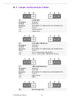
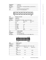
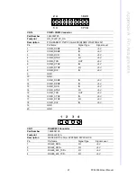
CN21
GPIO Connector
Part Number
1653010102
Footprint
JH10X1V-2M
Description
PIN HEADER 10*1P 180D(M)
DIP P=2.0mm
Pin
Pin Name
Signal Type
Signal Level
1
+V5_GPIO PWR
+5
V
2
DIO_IO0
I/O
+5 V
3
DIO_IO1
I/O
+5 V
4
DIO_IO2
I/O
+5 V
5
DIO_IO3
I/O
+5 V
6
DIO_IO4
I/O
+5 V
7
DIO_IO5
I/O
+5 V
8
DIO_IO6
I/O
+5 V
9
DIO_IO7
I/O
+5 V
10
GND
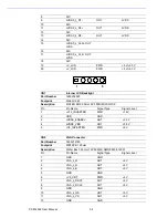
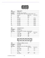
CN23
ATX Power In Connector
Part Number
1655303020
Footprint
WHL3V-2M
Description
WAFER BOX 2.0mm 3P 180D
w/LOCK
Pin
Pin Name
Signal Type
Signal Level
1
+V5_SB
PWR
+5 V
2
GND
3 PWR_PSON#
IN
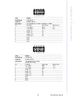
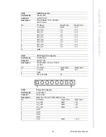
CN24
Power In Connector
Part Number
1655308120
Footprint
WHL8H-2M
Description
Wafer Box 2.0mm 8P 90D Male W/Lock
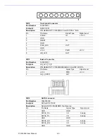
Pin
Pin Name
Signal Type
Signal Level
1
+V5_ATX
PWR
+5 V
2
+V5_ATX
PWR
+5 V
3 +V5_ATX
PWR
+5
V
4 GND
5 GND
6 GND
7 GND
8
+V12
PWR
+12 V
Summary of Contents for PCM-3362
Page 1: ...Data Modul AG www data modul com Specification PCM 3362 ...
Page 13: ...PCM 3362 User Manual 6 ...
Page 14: ...Chapter 2 2 Hardware Installation ...
Page 23: ...PCM 3362 User Manual 16 ...
Page 24: ...Chapter 3 3 AMI BIOS Setup ...
Page 44: ...Chapter 4 4 Software Introduction Installation ...
Page 55: ...PCM 3362 User Manual 48 ...
Page 56: ...Chapter 5 5 Chipset Software Installation Utility ...
Page 58: ...Chapter 6 6 Integrated Graphic Device Setup ...
Page 60: ...Chapter 7 7 LAN Configuration ...
Page 75: ...PCM 3362 User Manual 68 ...
Page 76: ...Appendix C C Mechanical Drawings ...
Page 81: ...PCM 3362 User Manual 74 ...
Page 82: ...Appendix D D Watchdog Timer and GPIO sample code ...


