50
Appendix B
– Start up and running information
Introduction
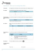
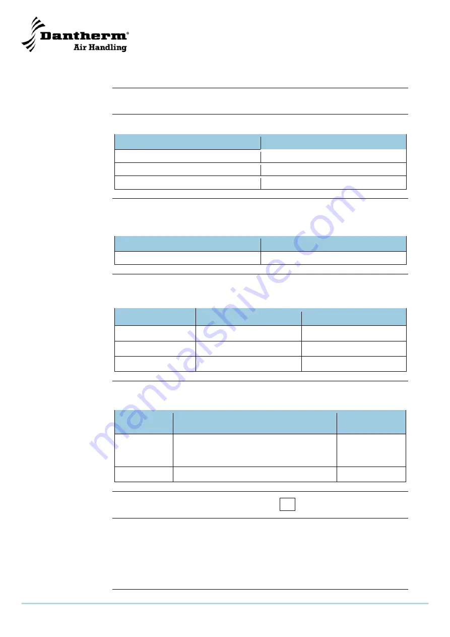
The tables below must be filled in by the service technician at the installation of the unit:
Fan speeds
The following fan speed settings have been made on this unit:
Fan step
Percentage
1
2
3
Relation between
supply and exhaust
fan
The unit has been adjusted to the following relation between supply and exhaust fan:
Setpoint
Percentage
Relation between supply and exhaust fan
Air volumes
Based on the above-mentioned settings, the unit has been adjusted to the following air
volumes:
Step
Exhaust air (m
3
/h)
Supply air (m
3
/h)
1
2
3
Temperature set-
points
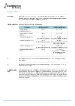
The unit has been adjusted to the following temperature setpoints:
Temperature
setpoint
Function
ºC
T
min
After-heat (if an electric heating element has
been mounted as accessory) when supply air
is lower than:
T
max
Summer mode when exhaust air is higher than
Environment
The unit is installed in a frost-free environment
Company, date and
signature
Company stamp
Date and signature
Summary of Contents for HRV 5
Page 1: ...Focus Trust Initiative HRV 5 Service manual DA GB DE No 039994 rev 2 0 08 03 2011...
Page 2: ...2005 layout...
Page 3: ...HRV 5 Service manual EN DA DE No 039994 rev 2 0 08 03 2011...
Page 54: ...52...
Page 104: ...52...
Page 138: ...36 Fortsetzung auf der n chsten Seite...
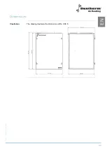
Page 148: ...46 Abmessungen Abbildung Die Abbildung zeigt die Abmessungen eines HRV 5...
Page 154: ...52 Firmenstempel Datum und Unterschrift...
Page 157: ...2005 layout...

