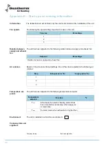
48
Wiring diagram,
continued
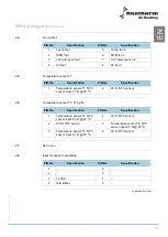
J9
Communication port:
PIN No.
Specification
PIN No.
Specification
1
12 VDC
5
-
2
TX
6
-
3
RX
7
-
4
0V
8
-
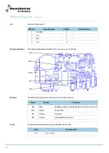
Diodes and fuse
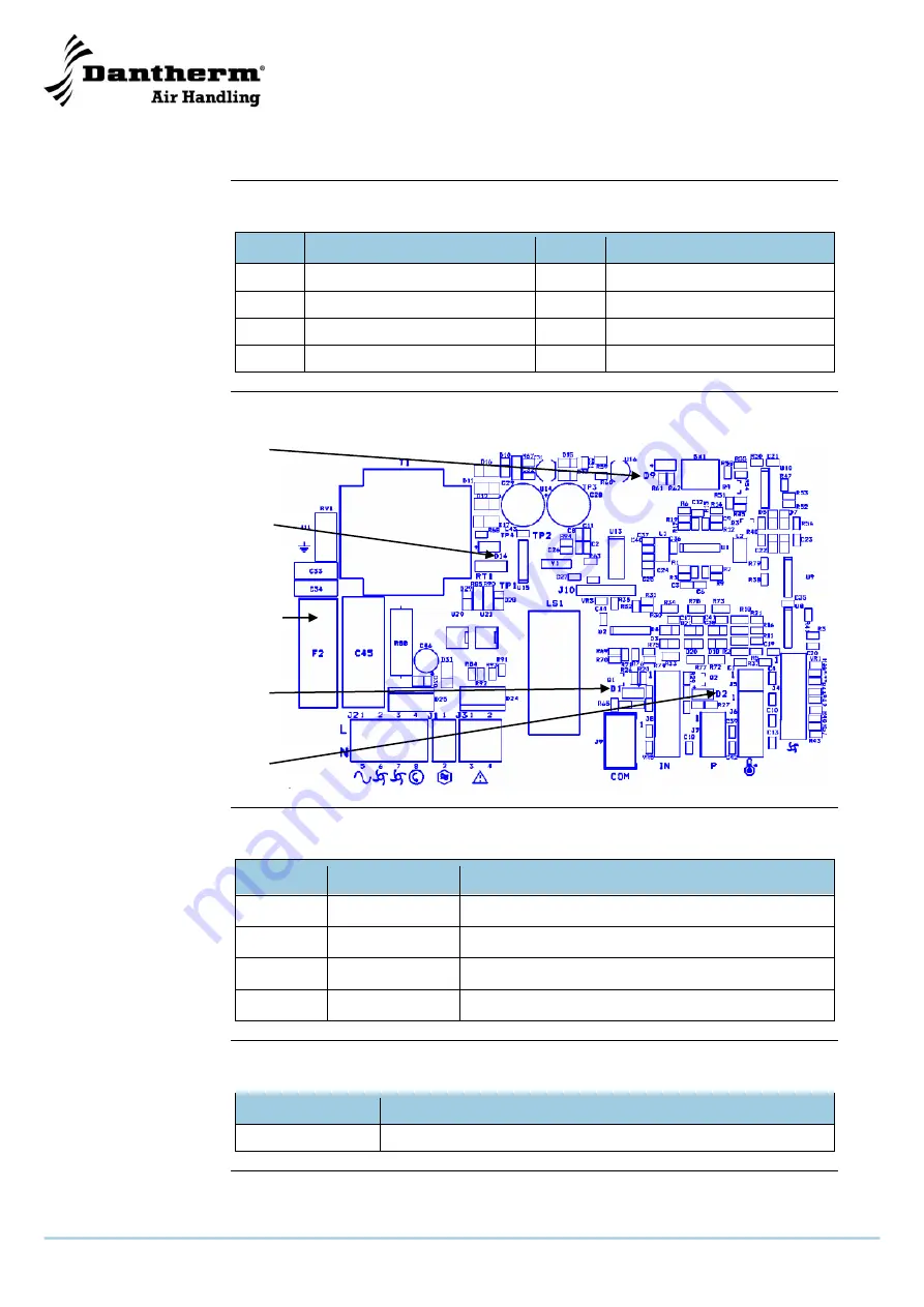
This drawing illustrates diodes and fuse on the control board:
D9
D14
Fuse
D1
D2
Diodes
The table below gives an overview of the diode functions:
Diode
Colour
Function
D9
Red
Software cycles (usually flashes once every second)
D14
Green
Power ON
D1
Yellow
Not used
D2
Yellow
Humidistat input active
Fuse
The table below describes the specification of the fuse:
Fuse
Specification
F2
4 A
– 250 V
Summary of Contents for HRV 5
Page 1: ...Focus Trust Initiative HRV 5 Service manual DA GB DE No 039994 rev 2 0 08 03 2011...
Page 2: ...2005 layout...
Page 3: ...HRV 5 Service manual EN DA DE No 039994 rev 2 0 08 03 2011...
Page 54: ...52...
Page 104: ...52...
Page 138: ...36 Fortsetzung auf der n chsten Seite...
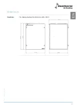
Page 148: ...46 Abmessungen Abbildung Die Abbildung zeigt die Abmessungen eines HRV 5...
Page 154: ...52 Firmenstempel Datum und Unterschrift...
Page 157: ...2005 layout...

