


executed. The input goes low whenever
the smart logic action [32] Set dig. out. A
low is executed.
[81]
SL Digital
Output B
See
parameter 13-52 SL Controller Action
.
The input goes high whenever the smart
logic action
[39] Set dig. out. Bhigh
is
executed. The input goes low whenever
the smart logic action
[33] Set dig. out. B
low
is executed.
[82]
SL Digital
Output C
See
parameter 13-52 SL Controller Action
.
The input goes high whenever the smart
logic action
[40] Set dig. out. C high
is
executed. The input goes low whenever
the smart logic action
[34] Set dig. out. C
low
is executed.
[83]
SL Digital
Output D
See
parameter 13-52 SL Controller Action
.
The input goes high whenever the smart
logic action
[41] Set dig. out. D
high is
executed. The input goes low whenever
the smart logic action
[35] Set dig. out. D
low
is executed.
[84]
SL Digital
Output E
See
parameter 13-52 SL Controller Action
.
The input goes high whenever the smart
logic action
[42] Set dig. out. E high
is
executed. The input goes low whenever
the smart logic action
[36] Set dig. out. E
low
is executed.
[85]
SL Digital
Output F
See
parameter 13-52 SL Controller Action
.
The input goes high whenever the smart
logic action
[43] Set dig. out. F high
is
executed. The input goes low whenever
the smart logic action
[37] Set dig. out. F
low
is executed.
[160] No alarm
The output is high when no alarm is
present.
[161] Running
reverse
The output is high when the frequency
converter is running counter clockwise
(the logical product of the status bits
running AND reverse).
[165] Local
reference
active
The output is high when
3-13 Reference
Site
=
[2] Local
or when
3-13 Reference
Site
=
[0] Linked to hand auto
at the same
time as the LCP is in
Hand
mode.
[166] Remote
reference
active
The output is high when
3-13 Reference
Site
=
[1] Remote or [0] Linked to hand/auto
while the LCP is in
Auto on
mode.
[167] Start
command
active
The output is high when there is an active
start command (that is via digital input,
bus connection, [Hand on] or [Auto on]),
and no stop command is active.
[168] Drive in hand
mode
The output is high when the frequency
converter is in
Hand
mode (as indicated by
the LED light above [Hand On].
[169] Drive in auto
mode
The output is high when the frequency
converter is in
Hand
mode (as indicated by
the LED light above [Auto on].
[180] Clock Fault
The clock function has been reset to
default (2000-01-01) because of a power
failure.
[181] Preventive
Maintenance
1 or more of the preventive maintenance
events programmed in
parameter 23-10 Maintenance Item
has
passed the time for the specified action in
parameter 23-11 Maintenance Action
[193] Sleep Mode
The frequency converter/system has
turned into sleep mode. See parameter
group
22-4* Sleep Mode
.
[194] Broken Belt
A broken belt condition has been
detected. This function must be enabled in
parameter 22-60 Broken Belt Function
[196] Fire Mode
The frequency converter is operating in
Fire mode. See parameter group 24-0*
Fire
Mode
.
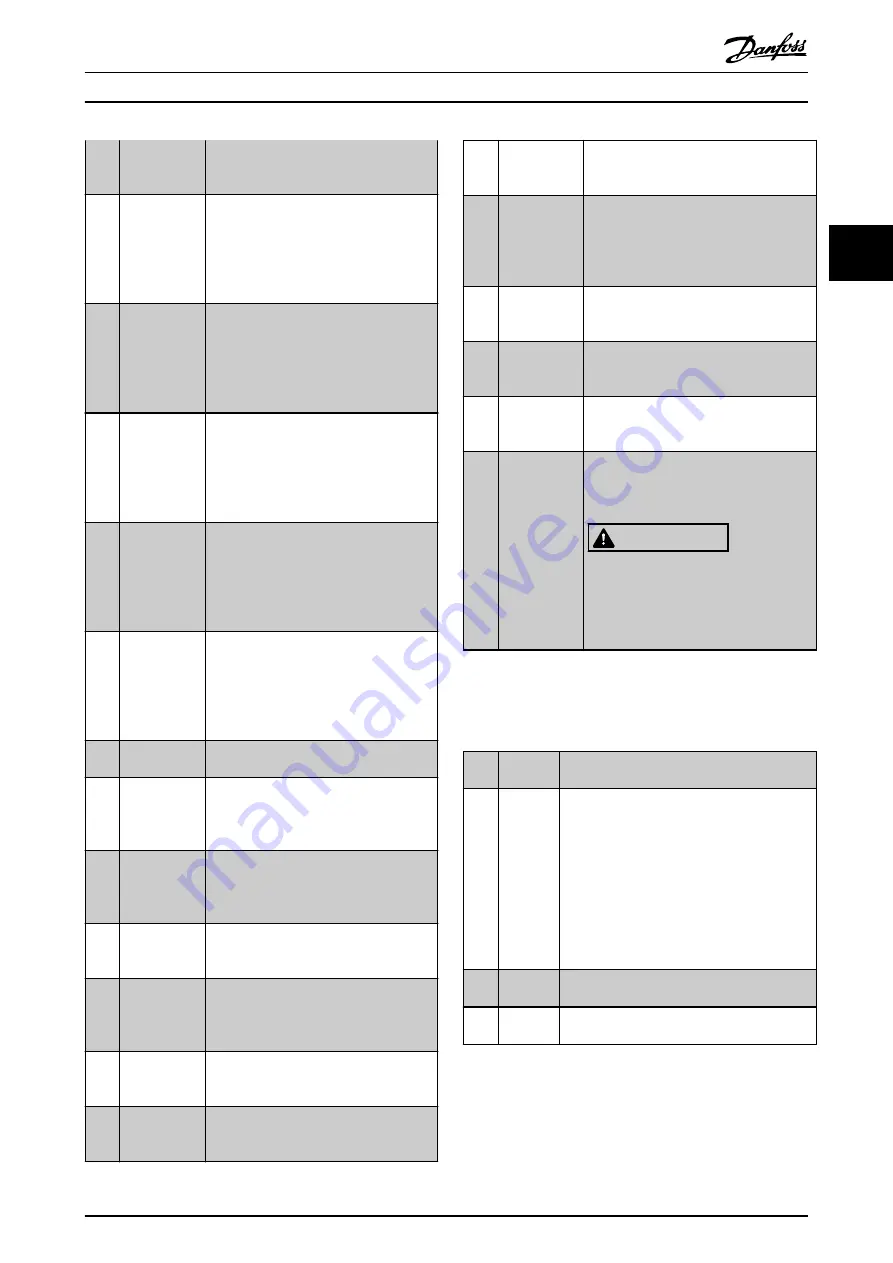
[198] Drive Bypass
To be used as signal for activating an
external electromechanical bypass,
switching the motor direct on line. See
24-1*
Drive Bypass
.
CAUTION
If enabling the drive bypass
function, the frequency converter is
no longer safety certified (for using
the Safe Torque Off in versions
where included).
The below setting options are all related to the cascade
controller.
Wiring diagrams and settings for parameter, see parameter
group
25-** Cascade Pack Controller
for more details.
[200] Full
Capacity
All pumps running and at full speed.
[201] Pump1
Running
1 or more of the pumps controlled by the
cascade controller are running. The function
also depends on
. If set to
[0] No
, Pump 1 refers to the
pump controlled by relay RELAY1 etc. If set to
[1] Yes
, Pump 1 refers to the pump controlled
by the frequency converter only (without any
of the built-in relays involved), and Pump 2 to
the pump controlled by the relay RELAY1. See
[202] Pump2
Running
See
[201] Pump1 Running
[203] Pump3
Running
See
[201] Pump1 Running
Parameter Descriptions
Programming Guide
MG11CE02
Danfoss A/S © 03/2015 All rights reserved.
75
3
3