


22-62 Broken Belt Delay
Range:
Function:
10 s [0 - 600
s]
Sets the time for which the broken-belt
conditions must be active before carrying out
the action selected in
.
3.20.6 22-7* Short Cycle Protection
When controlling refrigeration compressors, often there is a
need for limiting the numbers of starts. One way to do this
is to ensure a minimum run time (time between a start
and a stop) and a minimum interval between starts.
This means that any normal stop command can be
overridden by the
Minimum Run Time
function
(
parameter 22-77 Minimum Run Time
) and any normal start
command (start/jog/freeze) can be overridden by the
Interval Between Starts
function (
None of the 2 functions are active if
Hand On
or
Off
modes
have been activated via the LCP. If selecting
Hand On
or
Off
, the 2 timers are reset to 0, and not start counting until
Auto
is pressed and an active start command applied.
NOTICE
A coast command or missing run permissive signal
override both minimum run time and interval between
starts functions.
22-75 Short Cycle Protection
Option:
Function:
[0]
*
Disabled Timer set in
parameter 22-76 Interval between
is disabled.
[1]
Enabled Timer set in
parameter 22-76 Interval between
is enabled.
22-76 Interval between Starts
Range:
Function:
Size
related
*
[ par. 22-77
- 3600 s]
Sets the time desired as minimum
time between 2 starts. Any normal
start command (start/jog/freeze) is
disregarded until the timer has
expired.
22-77 Minimum Run Time
Range:
Function:
0 s
*
[ 0 - par.
22-76 s]
NOTICE
Does not work in cascade mode.
Sets the time desired as minimum run time
after a normal start command (start/jog/freeze).
Any normal stop command is disregarded until
the set time has expired. The timer starts
counting following a normal start command
(start/jog/freeze).
A coast (inverse) or an external interlock
command overrides the timer.
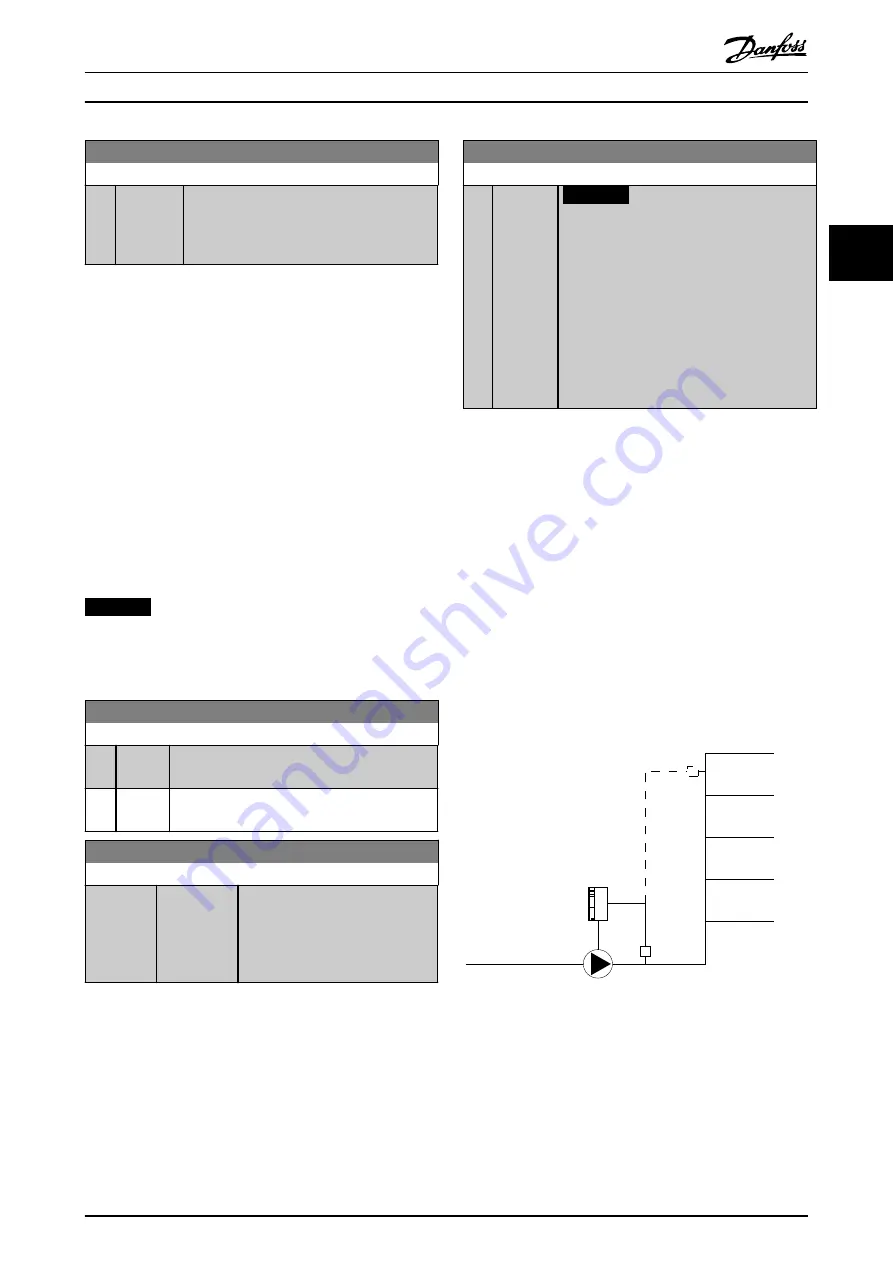
3.20.7 22-8* Flow Compensation
It is sometimes the case that it is not possible for a
pressure transducer to be placed at a remote point in the
system and it can only be located close to the fan/pump
outlet. Flow compensation operates by adjusting the
setpoint according to the output frequency, which is
almost proportional to flow, thus compensating for higher
losses at higher flow rates.
H
DESIGN
(required pressure) is the setpoint for closed loop
(PI) operation of the frequency converter and is set as for
closed-loop operation without flow compensation.
It is recommended to use slip compensation and RPM as
unit.
130BA383.11
Illustration 3.55 Flow Compensation
Parameter Descriptions
Programming Guide
MG11CE02
Danfoss A/S © 03/2015 All rights reserved.
169
3
3