


D. Operation keys and LEDs
13 [Hand On]: Starts the motor and enables control of the
adjustable frequency drive via the LCP.
NOTE!
Terminal 27 Digital Input (
) has coast inverse as default setting. This
means that [Hand On] will not start the motor if
there is no 24 V to terminal 27. Connect terminal 12
to terminal 27.
14 [Off/Reset]: Stops the motor (off). If in alarm mode the
alarm will be reset.
15 [Auto On]: The adjustable frequency drive is controlled
either via control terminals or serial communication.
Table 2.3
At power-up
At the first power-up, the user is asked to choose the
preferred language. Once selected, this screen will never
be shown again in the following power-ups, but the
language can still be changed in
130BB628.10
Select Language
[
0
] English
Set-up 1
Figure 2.2
2.3 Menus
2.3.1 Status
When choosing the [Status] menu it is possible to choose
between the following:
•
Motor Frequency (Hz),
16-13 Frequency
;
•
Motor Current (A),
16-14 Motor Current
;
•
Motor Speed Reference in Percentage (%),
16-02 Reference %
;
•
Feedback,
16-52 Feedback [Unit]
;
•
Motor Power (kW) (if
is set
to
[1] North America
, Motor Power will be shown
in the unit of hp instead of kW),
16-10 Power [kW]
for kW,
16-11 Power [hp]
for hp;
•
Custom Readout
16-09 Custom Readout
;
2.3.2 Quick Menu
Use the quick setup of the adjustable frequency drive to
program the most common VLT HVAC Basic Drive
functions. The [Quick Menu] consists of:
•
Wizard for open-loop applications
•
Closed-loop set-up wizard
•
Motor set-up
•
Changes made
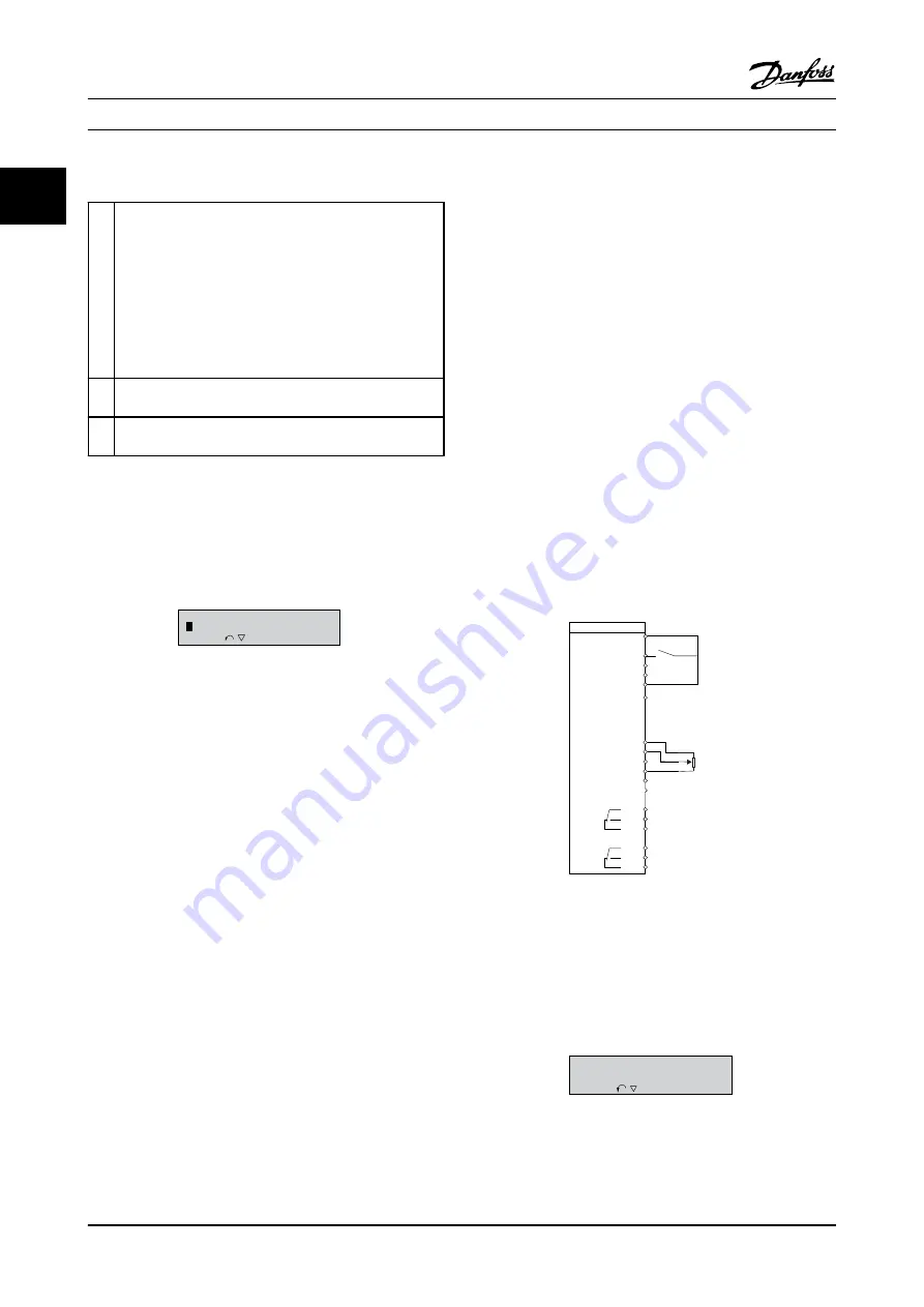
2.3.3 The FC101 Start-up Wizard for Open-
loop Applications
The built-in
wizard
menu guides the installer through the
set up of the adjustable frequency drive in a clear and
structured manner in order to set up an open-loop
application. An open-loop application is here an
application with a start signal, analog reference (voltage or
current) and optionally also relay signals (but no feedback
signal from the process applied).
FC
+24V
DIG IN
DIG IN
DIG IN
DIG IN
COM DIG IN
A OUT / D OUT
A OUT / D OUT
18
19
27
29
42
55
50
53
54
20
12
01
02
03
04
05
06
R2
R1
0-10 V
Reference
Start
+10V
A IN
A IN
COM
130BB674.10
45
+
-
Figure 2.3
The wizard will initially be shown after power-up until any
parameter has been changed. The wizard can always be
accessed again through the Quick Menu. Press [OK] to start
the wizard. If [Back] is pressed, the FC 101 will return to
the status screen.
130BB629.10
Press OK to start Wizard
Push Back to skip it
Set-up 1
Figure 2.4
How to Program
VLT
®
HVAC Basic Drive Programming Guide
2-2
MG18B222 - VLT
®
is a registered Danfoss trademark
2
2