


3.4.3 Example of How to Program the Speed Control
In this case, the speed PID control is used to maintain a constant motor speed regardless of the changing load on the
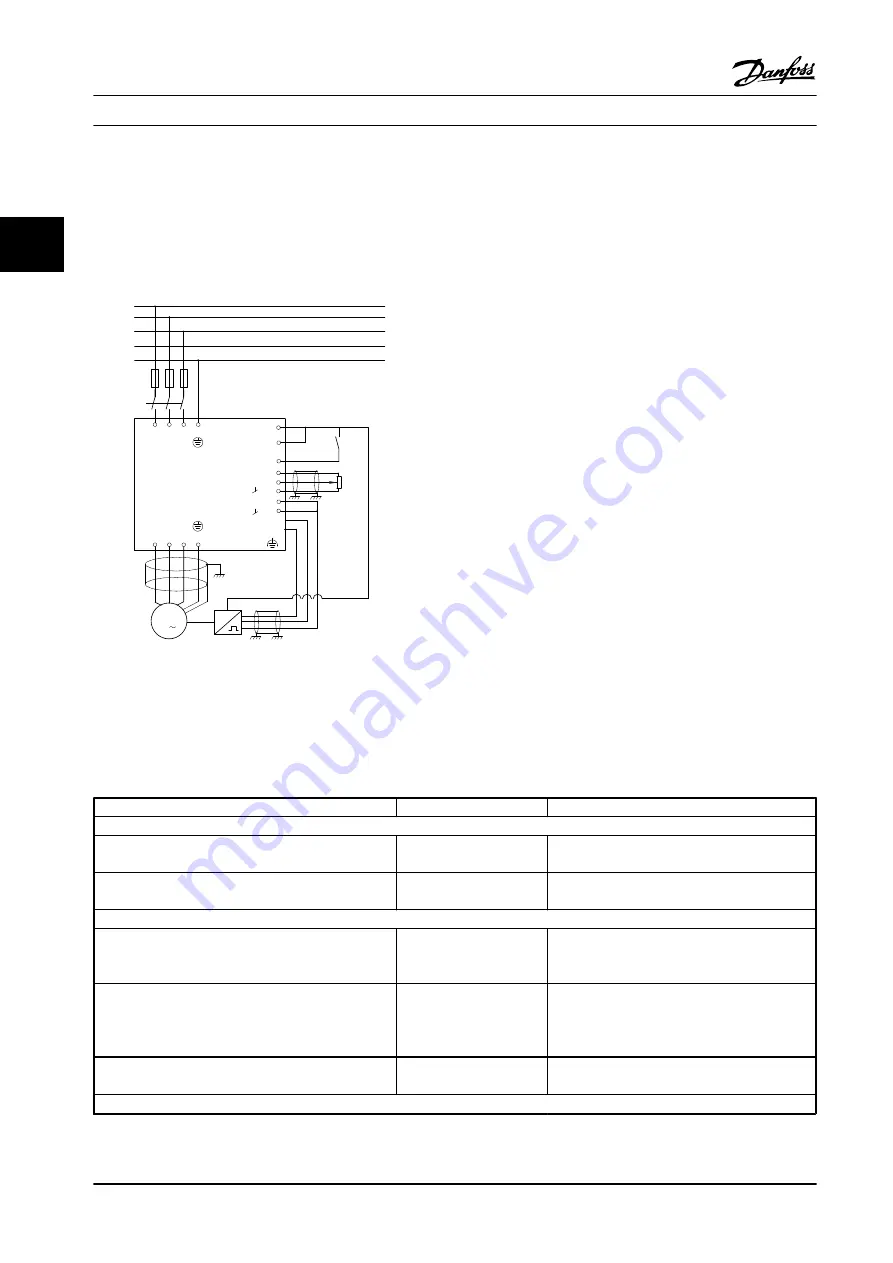
motor. The required motor speed is set via a potentiometer connected to terminal 53. The speed range is 0–1500 RPM
corresponding to 0–10 V over the potentiometer. Starting and stopping is controlled by a switch connected to terminal 18.
The Speed PID monitors the actual RPM of the motor by using a 24 V (HTL) incremental encoder as feedback. The feedback
sensor is an encoder (1024 pulses per revolution) connected to terminals 32 and 33.
M
3
96 97
99
98
91 92 93 95
50
12
L1 L2
L1
PE
L3
W PE
V
U
F1
L2
L3
N
PE
18
53
37
55
20
32
33
39
24 Vdc
130BA174.10
Figure 3.21 Speed Control Connections
3.4.4 Speed PID Control Programming Order
The following must be programmed in the order shown (see explanation of settings in the
VLT
®
AutomationDrive
Programming Guide
). In
, it is assumed that all other parameters and switches remain at their default settings.
Function
Parameter no.
Setting
1) To ensure the motor runs properly, do the following:
Set the motor parameters according to the nameplate
data.
1-2* Motor Data
As specified by motor nameplate
Perform Automatic Motor Adaptation (AMA).
1-29 Automatic Motor
Adaptation (AMA)
[1] Enable complete AMA
2) Check that the motor is running and that the encoder is attached properly. Do the following:
Press [Hand On]. Check that the motor is running and
note in which direction it is turning (henceforth referred
to as the “positive direction”).
Set a
positive
reference.
Go to
16-20 Motor Angle
. Turn the motor slowly in the
positive direction. It must be turned so slowly (only a
few RPM) that it can be determined if the value in
16-20 Motor Angle
is increasing or decreasing.
16-20 Motor Angle
N.A. (read-only parameter) Note: An increasing
value overflows at 65,535 and starts again at 0.
If
16-20 Motor Angle
is decreasing, then change the
encoder direction in
5-71 Term 32/33 Encoder Direction
.
5-71 Term 32/33 Encoder
Direction
[1] Counter-clockwise (if
16-20 Motor Angle
is
decreasing)
3) Make sure the drive limits are set to safe values.
Product Introduction
Design Guide
38
Danfoss A/S © Rev. 2014-02-10 All rights reserved.
MG34S222
3
3
Summary of Contents for VLT AutomationDrive FC 300
Page 2: ......