3-43
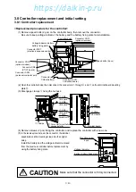
3.8 Controller replacement and initial setting
3.8.1 Controller replacement
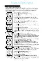
<Replacement procedure for the controller>
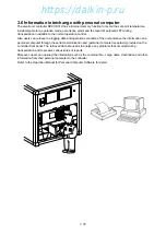
(1) Remove speed bolts (2 pcs) on the controller body, then remove the connector.
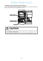
Be sure to keep voltage indicator, the battery and the battery fixing plate for reinstallation.
(2) Open the controller body, then disconnect the connectors
w
through
i
and
!1
on the terminal board mounting
plate
!0
.
(3) Disengage clamps
o
fixing the harness.
(4) Remove screws (2 pcs) fixing the controller, and replace the controller with a new one.
(5) In the reverse procedure, set the connector, the terminal
speed bolts and the mounting screws into the original
setup.
Install the battery and the voltage indicator removed
from the previous controller before replacement by
using the battery fixing plate.
Make sure that the connector is firmly connected.
CAUTION
Controller body
Voltage indicator, battery,
battery fixing plate
Connector CN11
(electronic expansion valve)
Connector CN16
(optional modem)
Connector CN15
(personal computer port)
Connector CN2
(PT/CT board)
Connector
CN26 (battery)
Connector CN15
(optional recorder)
Connector CN17
(indication board)
Speed bolts (2 pcs)
o
Clamps
w
CN3
I/O board
e
CN2
I/O board
r
CN1
I/O board
t
CN4
Adopter board
u
CN7
CPU board
!0
Terminal board
!1
Connector for ventilation
opening detector
i
CN6
CPU board
Mounting screw
4 pcs
Battery, battery fixing plate
Voltage indicator
https://daikin-p.ru

