background image

User’s  Manual   EM11A017

DCM601A71   intelligent Touch Manager

78


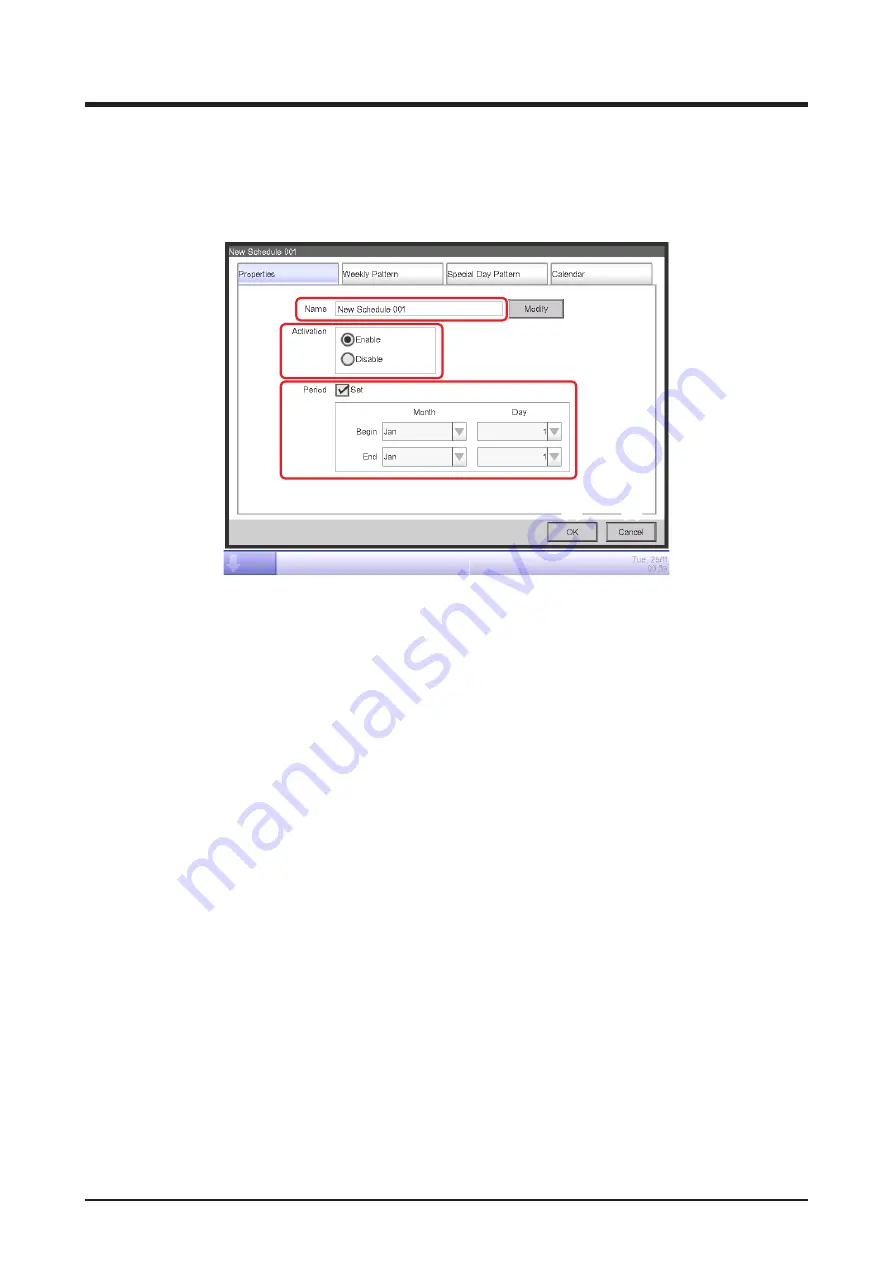
Properties Tab (Schedule Edit Screen)

This screen is displayed when you touch the Create, Copy, or Edit button on the main Schedule 

screen.  


It allows you to set up the name, validity period, and enable/disable the schedule program.

(1)

(2)

(3)

(4)

(5)

(1) 

Name text field

Displays the schedule program name.  


To change, touch the Modify button. Enter the new name in the Text Input dialog that appears.    

Set up a name using 1 to 32 characters, irrespective of single or double byte.  


Duplicate names are not permitted.

(2) 

Activation 

radio button

Enables/disables the schedule program.

(3) 

Period 

check box, combo box

Selecting the check box enables the combo box for entering the validity period.  


Select the start date and end date from the combo box. The selectable range for each combo 

box is as follows:

Month

: Jan, Feb, Mar, Apr, May, Jun, Jul, Aug, Sep, Oct, Nov, Dec 


Day

: 1 to 31 (Non-existing days cannot be selected)

(4) 

OK 

button

Saves the edit and closes the screen.

(5) 

Cancel 

button

Cancels the edit and closes the screen. Touching the button displays a confirmation dialog.

Summary of Contents for Intelligent Touch Manager DCM601A71

Page 1: ...User s Manual Model DCM601A71 DCM601A72 DCM601A73 DCM002A71 DCM008A71 MONITOR CPU ALIVE SLAVE MASTER BACKUP LAN SW SERVICE LAN FRONT BACK D MASTER ON OFF RESET LAN LINK D MONITOR...

Page 2: ...mful interference to radio or television reception which can be determined by turning the equipment off and on the user is encouraged to try to correct the interference by one or more of the following...

Page 3: ...accidents The following pictograms are used in this manual Never do Always follow the instructions given Keep wet hands away Keep water and moisture away WARNING Do not modify or repair the controlle...

Page 4: ...ing so may cause electric leakage and result in electric shocks or fire Never let the controller to get wet Water can cause damage to the controller and may cause an electric shock or fire NOTE Never...

Page 5: ...and Management Points 22 2 2 Displaying Areas and Management Points 22 2 3 Starting Stopping Areas and Management Points 23 2 4 Setting up the Operation Mode for an Indoor Unit 24 2 5 Setting up the...

Page 6: ...ng up a Schedule 61 Setting up a schedule program 61 Detailed screen and button descriptions 72 5 2 Setting up the Timer Extension Function 97 5 3 Setting up the Auto Changeover 99 Creating and editin...

Page 7: ...Functions 147 8 Setting up Automatic Control Functions 147 8 1 Setting up the Setback 147 8 2 Setting up the Interlocking Control 153 Interlocking Control Restrictions 156 Setting up an interlocking...

Page 8: ...the operation plan 249 Data output function 265 iTM integrator Explanation 273 12 iTM integrator 273 12 1 iTM integrator 273 Detailed screen and button descriptions 274 Cautions when using the iTM in...

Page 9: ...ng the iTM with computers in a LAN you can set up Web Remote Management and allow a maximum of 4 managers and 16 users to simultaneously access the iTM and if a connection to the Internet is available...

Page 10: ...emote Management Web Remote Management possible from network connected PC Maximum 4 administrators and 16 users can log in at the same time USB port iTM Emergency Stop signal input Power meter pulse i...

Page 11: ...ent points An All area to which you cannot manually register or delete members from is provided by default Maximum number of areas that can be created 650 All excluded Example Total number of manageme...

Page 12: ...ing Room Level 1 Level 2 Level 3 Level 4 Level 10 Management point A Aisle Management point A Management point A Aisle All Top Indoor Ventilator Dio Analog Pulse Outdoor Chiller Meeting Room A Example...

Page 13: ...harp edged items as this could damage the touch screen permanently 3 1 3 3 2 8 6 Standard View Icon Screen 5 4 5 7 Detailed Setup dialog The following describes how the text on each component displaye...

Page 14: ...ppear when there are hidden lines and columns To display hidden lines and columns press or slide the scroll bars To display truncated column text slide the column separation When sorting is enabled to...

Page 15: ...ion such as touch and select a grayed out component is not possible is displayed on buttons and the like when the label text is truncated due to space availability To display the label text completely...

Page 16: ...en status When the list opens upward Open status When a row is selected 7 Text box Text box When unfocused Text box When focused Cursor Indicates the position where the next character will be entered...

Page 17: ...r key buttons Key buttons for entering characters 2 Input area text box Displays the entered characters For the Password input dialog it displays asterisks 3 Shift key toggle button Toggles between up...

Page 18: ...the maximum permitted Missing Indicates the number of characters still necessary to comply with the minimum required 6 Keyboard switch combo box Toggles the keyboard between Special and Alph nm ltrs...

Page 19: ...n is set as the iTM display language a button to display the input list appears Touch the button to display a list of frequently used words and select the word to input Select a word and commit the se...

Page 20: ...econd year month day and hour minute depending on the entered data 3 Up Down button Increases or decreases the numeric value selected in the input area text box 2 by 1 10 1 or 10 4 AM PM setting combo...

Page 21: ...positive 4 Back button Deletes one digit at a time from the last number displayed in the input area text box 5 Clear button Completely deletes the numeric value displayed in the input area text box 6...

Page 22: ...71 intelligent Touch Manager 21 9 Input range label Displays the range of values that can be entered 10 OK button Touching this button commits the input 11 Cancel button Touching this button cancels t...

Page 23: ...een with the area and indoor unit names the operation mode setpoint and fan speed information appears For detailed operation see page 47 2 2 Displaying Areas and Management Points 1 2 1 Displays the h...

Page 24: ...stop 2 Selecting Start in the On Off combo box starts the selected area or management point while selecting Stop stops the selected area or management point The icon turns green or red depending on t...

Page 25: ...door unit for which you want to set up the operation mode 2 Touch the Setting button and display the Detailed Setup screen 3 Select the A C tab 4 Select the Operation Mode check box and select Fan Coo...

Page 26: ...set up the setpoint fan speed and airflow direction 2 Set up the setpoint in the Setpoint spin box and the Fan Speed using the buttons Low Middle High Automatic Available fan speed settings depend on...

Page 27: ...isplay the Detailed Setup screen 5 Select the A C tab 6 Select the Airflow Direction check box and set up the Airflow Direction using the buttons Air ow direction 0 Air ow direction 1 Air ow direction...

Page 28: ...ouch the Setting button and display the Detailed Setup screen 3 Select the R C Prohibition tab 4 You can permit prohibit the following remote controller operations a start stop b set up the operation...

Page 29: ...e and select Automatic ERVentilation or Bypass from the combo box 5 Select the check box for Ventilation Amount and select Auto normal Low normal High normal Auto fresh up Low fresh up or High fresh u...

Page 30: ...atic Ctrl tab on the Menu List screen 2 Touch the Schedule button and display the Schedule screen 3 Select the schedule program to check 4 Touch the Confirm button on the Schedule screen and display t...

Page 31: ...he Area button and display the Area Setup screen 3 Check settings in the Area List For detailed operation see page 117 Checking settings such as Mgmt Point Name Detailed Info and Icon 1 2 3 1 Select t...

Page 32: ...and display the Time DST Setup screen 3 On the screen the current time is displayed To change touch the Modify button 4 Enter the time in the Time Setup dialog that appears 5 Touch the OK button 6 To...

Page 33: ...You can use the and buttons to specify the date for which you want to check the history Alternatively you can display the Time Setup dialog by touching the Modify button and specify the date there 4...

Page 34: ...to FRONT 3 LAN SW Switch for toggling between the LAN socket on the rear and 2 SERVICE LAN socket 4 BACKUP Power ON OFF switch for settings backup 5 DIII MASTER Switch for setting up MASTER and SLAVE...

Page 35: ...n Switch for turning ON OFF the monitor The LED color changes as follows each time the key is pressed Off The power is turned off On Orange The monitor is turned off On Green The monitor is turned on...

Page 36: ...the list of menu items Sets up weekly and annual schedules Sets up a weekly schedule for each day Sets up schedules for special days such as extra holidays Sets up the off timer to prevent failure to...

Page 37: ...ting stopping management points in conjunction with other equipment Sets up an arbitrary emergency stop program Function for keeping the room temperature within a certain range Function for controllin...

Page 38: ...Operation Mgmt and Energy Navigator optional tabs The button changes to Close while the Menu List screen is being displayed 3 Standard View switch button Switches from the Layout View screen optional...

Page 39: ...entered into waiting for release status automatically without the icon being touched even once The balloon is not displayed if the target unit was put into waiting for release status manually by touch...

Page 40: ...the error code NOTE 14 Details button Displays the Detailed Setup screen for the selected area or indoor unit 15 On Off Combo box Starts Stops the selected area or management point When the optional S...

Page 41: ...ange the settings on each tab select the relevant check boxes To commit the settings touch the OK button For items for which manual setup is prohibited you can only reset the filter sign Common Tab Se...

Page 42: ...the management point from the remote controller will be enabled or disabled Permitted Enabled Stop Only Only stopping is enabled Prohibited Disabled 2 Operation Mode Sets up whether changing the opera...

Page 43: ...Heat Dependent Automatic and Dry Dependent means either Cool or Heat This is because the operation mode follows the Cool or Heat operation mode set up in the air conditioner with Changeover option Set...

Page 44: ...ction 3 Air ow direction 4 Swing 6 Setpoint Restriction Use this setting when limiting the setpoint range that can be set up from the remote controller Cooling Limit Sets up the setpoint range for the...

Page 45: ...entilation Mode Select and set up a ventilation mode from Automatic ERVentilation and Bypass This setting may not be available depending on the model NOTE 2 Ventilation Amount Select and set up a vent...

Page 46: ...at Mode for Dio and select and set up a repetition interval in the 1 to 10 minute range in increments of 1 minute If starting or stopping the Dio fails when the Repeat Mode is enabled the attempt to s...

Page 47: ...the ID of the area or management point 3 Detailed Type field Displays the type of the area or management point 4 Port No field Displays the port number to which the management point is connected Not d...

Page 48: ...rl System Settings Operation Mgmt and Energy Navigator optional tabs 3 Standard View switch button Switches from the Layout View screen optional to the Standard View screen 4 Layout View switch button...

Page 49: ...nt points are displayed using icons 11 Information button Displays the legend for an icon or contact information for inquiries regarding the system 12 Selected area management point status Displays th...

Page 50: ...or the indoor unit of the selected area or the selected indoor unit Low Middle High Automatic 18 Setting button Displays the Detailed Setup screen for the selected area or management point 19 Header E...

Page 51: ...ton Switches to the Menu List screen which consists of Automatic Ctrl System Settings Operation Mgmt and Energy Navigator optional tabs 2 Standard View switch button Switches from the Layout View to t...

Page 52: ...screen To move touch the scope and drag 12 Layout selection list The title selected in this list is the displayed layout 13 Back button Displays the previous screen again 14 Information button Displa...

Page 53: ...dden unless the option is enabled NOTE 1 Schedule Allows you to set up weekly as well as annual schedules including special holidays by setting up the time to start stop air conditioners by the day of...

Page 54: ...ain range It only works in Cool mode 7 HMO Optional function This function automatically starts stops the indoor unit when it is operating in Heat mode This function avoids unnecessary rise in the roo...

Page 55: ...an set up to 10 hierarchical levels 2 Mgmt Pts Changes the name detailed information and icon of management points 3 Maintenance Sets up a management point maintenance 4 Network Sets up the network IP...

Page 56: ...Touch Panel Calibration Corrects the contact points of the touch panel 11 Time DST Sets up the current time and the daylight saving time 12 Regional Sets up the language to use date and time format un...

Page 57: ...control information etc You can also output history to a USB memory in CSV format 2 PPD Optional function This function calculates and displays the proportional distribution to each air conditioner of...

Page 58: ...of the actual consumption over the planned energy consumption per year month on a graph and the like You can also compare this year s actual consumption with that of last year s 2 Equipment op Mgmt Th...

Page 59: ...n button 11 on the Standard View screen see page 37 page 47 or the Information button 14 on the Layout View screen see page 50 The Information screen consists of the Legend and Contact tabs Legend Tab...

Page 60: ...there is at least one management point with communication error in the area When there is at least one management point in emergency stop in the area When all management points are in mainte nance in...

Page 61: ...User s Manual EM11A017 DCM601A71 intelligent Touch Manager 60 Contact Tab 1 1 Displays contact information set up by the service person...

Page 62: ...e heat On Off Setback Operation Mode Indoor unit Ventilator Chiller Dio Ao Area Target Fan Speed Setpoint Setpoint shift Ventilation mode Ventilation amount Indoor unit Ventilator Chiller Dio Ao Area...

Page 63: ...he Automatic Ctrl tab of the Menu List screen and display the Schedule screen see page 52 1 1 Setting up the schedule program name Touch the Create button 1 and display the Schedule Edit screen The Sc...

Page 64: ...ting up the operation start time on Monday Touch to display the Weekly Pattern tab 3 4 Select Monday using the Day of the week radio button 3 Touch the Edit button 4 to display the Event List screen 5...

Page 65: ...00 AM9 00 when using 12 hour clock and touch the OK button to return 3 Setting up the target Touch the Modify button 7 to display the Mgmt Point Area dialog The Mgmt Point Area dialog consists of two...

Page 66: ...adio button To set up the operation mode and setpoint touch and display the A C tab 9 10 11 Select the Operation Mode check box 9 and then Cool from the combo box Select the Setpoint check box 10 and...

Page 67: ...e list The step above finishes the setup of the event Start cooling Office A to setpoint 82 F from 9 00 on Monday 5 Setting up the operation stop time Select the event Start cooling Office A to setpoi...

Page 68: ...io button 14 Touch the OK button and return to the Event List screen The step above finishes the creation of the schedule Cool Office A to setpoint 82 F from 9 00 to 18 00 on Monday Touch the OK butto...

Page 69: ...estination from the list 16 Select Tuesday Wednesday Thursday and Friday Touch the OK button to overwrite the events and return to the Schedule Edit screen The step above finishes the creation of the...

Page 70: ...button 18 to display the Name Input dialog Enter Working day for name and touch the OK button to rename the special day 2 Setting up the operation start stop times operation mode and setpoint Touch t...

Page 71: ...ay of the week Saturday Touch the Add button to register the special day pattern It appears in 22 To preview the calendar with the special day pattern touch the Preview button 23 Touch the Close butto...

Page 72: ...rties tab on the Schedule Edit screen 24 Select the Enable radio button 24 and enable the Program for Office This completes the creation of the schedule program Touch the OK button to save and return...

Page 73: ...s well as copy a calendar 5 1 3 4 2 6 7 8 9 10 11 1 Schedule Info view area Displays registered schedule programs 2 Selected schedule view area Displays information of the program selected in the Sche...

Page 74: ...ram selected in the Schedule Info view area Touching the button displays a deletion confirmation dialog 9 Edit button Displays the Schedule Edit screen that allows you to edit the program selected in...

Page 75: ...of registered schedule programs in order of its registration 2 Selected schedule view area Displays information of the program selected in the Schedule Info view area 3 Icon button Switches the scree...

Page 76: ...ram selected in the Schedule Info view area Touching the button displays a deletion confirmation dialog 9 Edit button Displays the Schedule Edit screen that allows you to edit the program selected in...

Page 77: ...Icon view 1 Icon Displayed information Icon of scheduled program Validity period of scheduled program Upper Left Start date Lower right End date Name Icon type Disabled Without validity period With va...

Page 78: ...1 Schedule Settings list Displays the list of events for the date indicated in the Date area 2 for the selected schedule program 2 Date area Displays the date and day of the week for which the events...

Page 79: ...up a name using 1 to 32 characters irrespective of single or double byte Duplicate names are not permitted 2 Activation radio button Enables disables the schedule program 3 Period check box combo box...

Page 80: ...hedule set for the day of the week selected with the radio button will be copied 4 Delete button Deletes the schedule set to the day of the week selected with radio button Touching the button displays...

Page 81: ...Copy to Selection screen that allows you to select the destination to which the schedule set for the special day selected with the radio button will be copied 4 Delete button Deletes the schedule set...

Page 82: ...egends available in the Schedule Settings view area SB Low and SB High are displayed only when the optional setback function is enabled 8 OK button Saves the edit and closes the screen 9 Cancel button...

Page 83: ...maximum of 40 special day patterns in one calendar 2 Order button Moves up and down the order of the special day pattern selected in the Calendar Settings list 3 Delete button Deletes the special day...

Page 84: ...ecial day pattern 8 Preview button Previews the calendar with the registered special day in the Calendar Settings list 9 OK button Saves the edit and closes the screen 10 Cancel button Cancels the edi...

Page 85: ...ence when setting the calendar If two or more special days set using the Date setup combo box overlap for example single day designation overlaps with a period designation the latter lower in the list...

Page 86: ...which to select the destination of the copy 3 Preview radio button Selects the schedule to be displayed in the Calendar view area You can select the schedule program source of the copy or a schedule p...

Page 87: ...elected in the Schedule Edit screen 3 Back button Moves the Event list view to that of the previous day of the week special day 4 Next button Moves the Event list view to that of the next day of the w...

Page 88: ...User s Manual EM11A017 DCM601A71 intelligent Touch Manager 87 9 OK button Saves the edit and closes the screen 10 Cancel button Cancels the edit and closes the screen...

Page 89: ...you to copy events set up for a day of the week special day to another day of the week special day 2 3 4 1 1 Copy from text field Displays the name of day of the week special day selected in the Sche...

Page 90: ...event s operating time Touch the Modify button and enter the time in the Time Input dialog that appears The range of values you can enter is 00 00 to 23 59 AM00 00 to PM11 59 when using 12 hour clock...

Page 91: ...as the function learns from repeated use When Pre Cool Pre Heat is set up for an area the operation mode the setpoint set up in the Pre Cool Pre Heat settings and the order to start are sent to the m...

Page 92: ...ignored and the normal schedule will be executed When the daylight saving time starts or ends Pre cool heat may not be executed or may be executed twice depending on the time setting When using an air...

Page 93: ...troller Select the setting from Permitted Stop Only and Prohibited 2 R C Operation Mode permission prohibition setting area Restricts changing the operation mode from the remote controller Select the...

Page 94: ...ouch the Modify button and enter the temperature in the Numerical Input dialog that appears The range of values you can enter is 22 to 158 F in increments of 1 F If you selected Setpoint shift select...

Page 95: ...The fan speed you can set depends on the target 4 Timer Extension setup area Sets up the function that prevents failure to turn off the indoor unit Select whether to enable On or disable Off the func...

Page 96: ...to set up and select the setting from the combo box 1 Ventilation Mode setting area Sets up the ventilation mode Select the setting from Automatic ERVentilation and Bypass 2 Ventilation Amount setting...

Page 97: ...et up and enter the setting using the Modify button 1 Analog Value setting area Sets up an analog value Touch the Modify button and enter the analog value in the Numerical Input dialog that appears Th...

Page 98: ...indoor unit encounters the communication error or maintenance has been started the counted Duration will be cleared NOTE 1 Touch the Timer Extension button on the Automatic Ctrl tab of the Menu List...

Page 99: ...multaneously set up the air conditioners may be stopped before the time set up by this function preventing the temperature to reach the setpoint at the set time Example 1 Duration is set to 30 minutes...

Page 100: ...the setpoint is changed an assessment is performed immediately and then once every 5 minutes The assessment of the control condition is performed according to the following four patterns depending on...

Page 101: ...3 4 F Cooling mode Heating mode Heating mode Cooling mode Heating mode Heating mode Cooling mode Representative suction temperature When Representative suction temperature Representative setpoint Heat...

Page 102: ...3 F 3 F Representative setpoint Cool Thermal difference in 0 F 3 When the thermal difference is 0 F Heating mode Cooling mode Cooling mode Heating mode Heating mode Heating mode Cooling mode The foll...

Page 103: ...a management point that is not registered in any group based on the affiliation information displayed in 7 Selecting a management point from 6 and touching the Remove button cancels its registration...

Page 104: ...ger 103 Setting up the changeover conditions 9 10 1 Select a group in 9 and touch the Attributes button 10 to display the Attributes dialog box 11 12 13 2 Touching the Modify button in 11 displays the...

Page 105: ...point In this mode information of the indoor unit registered at the top is used even when that indoor unit is stopped However this function does not work if the operation mode of that indoor unit is o...

Page 106: ...on radio button 15 To disable select Disable Cautions when Using Simultaneously with Other Control Functions 1 If the cooling setpoint is lowered by the Sliding Temperature function when this function...

Page 107: ...work as intended with the settings Example When the method for referencing room temperature and setpoint is set up to Fixed and the thermal difference to 7 F 1 Heating starts with setpoint for the ind...

Page 108: ...mistake during maintenance you can recover the iTM forcibly The following describes how to interpret the Emergency Stop view and release an emergency stop If the optional function is enabled you can d...

Page 109: ...the program to release and touch the Release button 4 Only Default is displayed for programs if the optional function is disabled To confirm and release the emergency stop touch the Yes button on the...

Page 110: ...e as follows Creating and deleting an area 1 Touch the Area button on the System Settings tab of the Menu List screen and display the Area Setup screen see page 54 1 2 3 2 1 on the Area Setup screen i...

Page 111: ...newly created area is created under existing management points and areas You will not be able to create new areas in the following cases The number of areas exceeds 650 The area selected in the Area...

Page 112: ...01A71 intelligent Touch Manager 111 Example To delete the Meeting Room Area Setup Screen Area Management point 1F North 1F South Meeting Room Aisle Room A Room B Of ce Lighting A Lavatory Building A T...

Page 113: ...ation dialog that appears deletes the selected area 1F North 1F South Meeting Room Aisle Room A Room B Of ce Area Setup Screen Lavatory Lighting A Building A Top All Indoor Ventilator 6 1 is the list...

Page 114: ...a you want to move for example Meeting Room and touch the Move button 5 to display the Area Move screen The area to move and lower level areas for example Meeting Room Room A Room B and Room B1 are no...

Page 115: ...is displayed under the area selected in step 2 for example 1F North Top All and areas immediately under All cannot be moved You cannot move an area into these areas either NOTE Registering a manageme...

Page 116: ...ister move them using the Add button To change the display order change the order in which 7 is displayed using the buttons 9 To delete a member select it from 7 and then touch the Remove button The A...

Page 117: ...move and touching the Jump button 10 displays the Order Setup screen 11 4 11 is the list of management points and areas that were not selected in the Area Member Registration screen Select the destin...

Page 118: ...n of an area 12 1 Select the area to name and set up the detailed information from the Area Setup screen and touch the Attributes button 12 to display the Area Attribute Setup screen 13 14 2 Touch the...

Page 119: ...management points and areas in the order they are listed in the Area Member Registration screen 15 16 1 Touch the Modify buttons 15 and 16 on the Area Attribute Setup screen Enter the interval for sta...

Page 120: ...1 intelligent Touch Manager 119 Setting up icons 17 1 Touch the Modify button 17 on the Area Attribute Setup screen to display the Icon Setup screen 2 Select an icon from the displayed icon list and t...

Page 121: ...file in the iTM unit and touch the Load button 19 on the Area Setup screen A confirmation dialog with the message Loaded data will delete existing data Max Time 15 sc will appear Touching the Yes butt...

Page 122: ...anagement points The following describes how to set this up 1 Touch the Mgmt Pts button on the System Settings tab of the Menu List screen and display the Mgmt Points Setup screen see page 54 1 2 2 1...

Page 123: ...sage Same Mgmt Point name is already registered appears and it is rejected Touch the Modify button 5 for Detailed Info Enter the detailed information in the Text Input dialog that appears The maximum...

Page 124: ...the Password dialog to enter the password for unlocking the screen When administrator password and screen lock are simultaneously enabled entering the administrator password after touching the Menu Li...

Page 125: ...5 alphanumeric characters The dialog will appear again Enter the password again for confirmation Touch the OK button to save and close the screen 4 To change the administrator password or the screen l...

Page 126: ...The following describes how to set this function up 1 Touch the Maintenance button on the System Settings tab of the Menu List screen and display the Maintenance Settings screen see page 54 2 1 2 To s...

Page 127: ...language used in the iTM unit 1 Touch the Regional button on the System Settings tab of the Menu List screen and display the Locale screen see page 54 1 2 Select the display language Touch the Modify...

Page 128: ...elect the temperature unit from Fahrenheit and Celsius using the Celsius Fahrenheit radio button 5 Select the decimal point and separator for the CSV file using the Decimal Point CSV Separation radio...

Page 129: ...tton and close the screen Entering an inappropriate value displays an error dialog where you will be able to enter the correct value 3 When using daylight saving time enable it in 3 and select the sta...

Page 130: ...ing Backlight Off will turn off the screen when the idle time set in step 3 elapses Touch the Preview button 2 to preview the selected screensaver Touch the screen to return to the Screensaver screen...

Page 131: ...e 54 1 2 3 2 In the Screen Luminance combo box 1 select and set the luminance level for the iTM screen to a value between 1 and 8 3 In the Buzzer combo box 2 select and set the volume for the buzzer t...

Page 132: ...rms the start stop operation performed from the iTM Standard View screen Con rmation dialog 1 Touch the Confirmation Dialog button on the System Settings tab of the Menu List screen to display the Con...

Page 133: ...play the touch panel calibration screen see page 54 1 2 A cross 1 will appear 5 times on the screen Touch the center of each cross in order You can start the calibration again by touching a point far...

Page 134: ...or less The iTM supports USB2 0 1 Touch the Backup button on the System Settings tab of the Menu List screen see page 54 2 When the dialog that confirms the start of the backup is displayed connect t...

Page 135: ...information displayed is as indicated below 1 Touch the Version Info button on the System Settings tab of the Menu List screen to display the Version Information screen see page 54 1 2 3 4 5 2 The in...

Page 136: ...rmat 1 Touch the History button on the Operation Mgmt tab of the Menu List screen and display the History screen see page 56 A Wait dialog is displayed while the history is being acquired NOTE 1 3 4 5...

Page 137: ...vious day and touch the button to display the history records of the next day Touching the Show Updates button 5 displays in 1 the latest 100 history records of the type specified in 3 as well as the...

Page 138: ...Emergency Stop Settings of programs registered with the Emergency Stop Auto Changeover Settings of programs registered with the Auto Changeover Temperature Limit Settings of groups registered with the...

Page 139: ...iTM version Program Name Program name Enable Disable Program enabled disabled Enable Disable Period Validity period of the program All is output when the Schedule is enabled for all term Sun Time P A...

Page 140: ...the Special day 5 Time P A Name Action Special Day Name of the Special day 1 Date or Month Day of the week setting of Special day 1 Month day Name of the Special day 2 Date or Month Day of the week s...

Page 141: ...t Touch Manager 140 A B C D Calendar Preview Week Date 1 2 3 Year Month Ditto Ditto Ditto Ditto Ditto Ditto Ditto Ditto Ditto Ditto Ditto Ditto Blank Program Name The settings of the second or subsequ...

Page 142: ...itto Ditto Ditto Output 1 Detection Conditions Input condition for interlocked output Start Stop Interval sec Sequential start stop interval P A Name Action Area Mgmt Point Area Management point name...

Page 143: ...le Program enabled disabled Enable Disable Input Release Mode Release mode Automatic Manual Mgmt Point Input signal s management point name Ditto Output Specification method Output method Listed Point...

Page 144: ...cluded in the group Ditto Blank Group Name Group name Enable Disable The settings of the second or subsequent program will be output following above Temperature Limit CSV file format Shadowed data are...

Page 145: ...or Temperature Range Outdoor temperature range Upper limit Lower limit Setpoint Range Setpoint range Upper limit Lower limit Mgmt Point Name of management point included in the group Ditto Blank Group...

Page 146: ...e disable Enable Disable Set up excluded time Mon Ditto Ditto Tue Ditto Ditto Wed Ditto Ditto Thu Ditto Ditto Fri Ditto Ditto Sat Ditto Ditto Exceptions to Excluded Time Normal Exceptions to Excluded...

Page 147: ...r name Export Date Output date iTM Version iTM version Cool Recovery Temp Cool Recovery Temp Heat Recovery Temp Heat Recovery Temp High Relative Setup Setpoint Setback High Relative Setup Setpoint Hig...

Page 148: ...t one or both depending on your needs Setpoint Time During absence During presence During absence Setup setpoint upper limit setpoint during absence lower limit setpoint during absence Cool setpoint d...

Page 149: ...k Setpoint the indoor unit is stopped 2 Room temperature is continuously monitored and when it becomes lower than the Setpoint Relative Setback Setpoint the indoor unit is started again 3 Thereafter w...

Page 150: ...ndoor unit is stopped by the Timer Extension function when setback is active NOTE The following describes how to set this up 1 Touch the Temp Setback button on the Automatic Ctrl tab of the Menu List...

Page 151: ...ecovery temperature for heating in the Heat Recovery Temp combo box 7 The range of values you can select from is 2 to 10 F in increments of 1 F When finished touch the OK button to return to the Setba...

Page 152: ...nting the function may also not work even if a higher value than the Relative Setback Setpoint or Relative Setup Setpoint is set Temperature Limit Since Temperature Limit is a function that works when...

Page 153: ...reated as ON Setback Inactive Not treated as OFF Sliding Temperature HMO Setback Active Not treated as ON Setback Inactive Treated as OFF Timer Extension Start order by Setback Not treated as start tr...

Page 154: ...to detect and required conditions are as indicated in the tables below Management point type Switch Equipment error Analog upper lower limit error Operation mode Analog value Target management point I...

Page 155: ...on is On and required duration 15 minutes On Success Time On Off status Success Failure Success assessment Required duration cleared not cleared Failure Success 15 minutes 15 minutes 15 minutes Condit...

Page 156: ...door unit Ventilator Ventilator Chiller Chiller Dio D3Dio External Dio BACnet Dio Analog Ao External Ao BACnet Ao Area All Target management point type Fan Speed Setpoint Setpoint shift Switch by remo...

Page 157: ...f start The initial status of a target input management point when started is handled as unfixed Similarly to the case above the changes in status before and after unfixed are not viewed as triggers o...

Page 158: ...When input 1 00 and input 1 01 simultaneously change from OFF to ON the controller may detect two statuses as indicated in the gure below Output 1 02 ON Output 1 02 OFF Temporarily outputs ON Status 2...

Page 159: ...am Output1 When either indoor unit a or indoor unit b goes on turn on Ventilator c The required duration is 10 minutes Output2 When both indoor unit a and indoor unit b go off turn off Ventilator c Cr...

Page 160: ...e Detection Condition combo box 4 displays a list of management points 5 for which On Off can be registered as the condition to be detected Selecting the indoor unit a and touching the Add button regi...

Page 161: ...rn to the Interlock Program Input screen Similarly set up the indoor unit b 9 Select the indoor unit a and touch the Timer min button 9 and enter 10 for required duration in the Numerical Input dialog...

Page 162: ...her indoor unit a or b to be On for 10 minutes 4 Setting up the target Touch the Modify button 12 and display the Interlock Program Output Setup screen 14 15 13 13 is the list of management points and...

Page 163: ...h Manager 162 16 Select the On Off check box 16 on the Common tab and then select the Start radio button Touch the OK button and return to the Interlock Program Output Setup screen Touch the OK button...

Page 164: ...t action for the same condition to detect and target Select the Output2 tab 17 and then All inputs become invalid in the Input condition combo box 18 Touch the Modify button 19 and display the Interlo...

Page 165: ...Manager 164 23 Select the Stop radio button 23 and touch the OK button to return to the Interlock Program Output Setup screen Likewise touch the OK button on the Interlock Program Output Setup screen...

Page 166: ...go off The Ventilator control program is now complete Touch the OK button and return to the main Interlocking Control screen Enabling the Interlocking Program Enable the created interlocking program...

Page 167: ...tered interlocking programs 2 Enable Disable radio button Enables and disables an interlocking program 3 Create button Creates a new interlocking program Touching the button displays the Name Input di...

Page 168: ...enames the program selected in the interlocking program list Touching the button displays the Text Input dialog 7 Edit button Displays the Interlock Program Setup screen that allows you to edit the pr...

Page 169: ...least one input becomes valid All inputs become valid At least one input becomes invalid and All inputs become invalid 5 Modify button Output Displays the Interlock Program Output Setup screen that a...

Page 170: ...agement Point Input list 4 Available Management Points list Displays a list of management points that can be selected as input for the condition to detect selected in the Detection Condition combo box...

Page 171: ...screen opens on the tab that corresponds to the type of the monitored management point Start Stop Error Tab Condition Setup Screen This screen is displayed when you touch the Start Stop Error tab on...

Page 172: ...n the Condition Setup screen Sets up the conditions required for the operation mode to be detected 1 2 3 1 Operation Mode combo box Select the operation mode required for clearing the condition Select...

Page 173: ...radio button Select the inequality sign to be used in the analog value condition from and 3 Analog Value2 field Sets up the right side of the analog value condition a Constant Value area Select this...

Page 174: ...offset For the range of values you can enter see page 178 4 Hysteresis area Sets up the range of the dead zone Touch the Modify button and enter the range in the Numerical Input dialog that appears Fo...

Page 175: ...minute In addition you can set a hysteresis around the valid invalid border value to prevent hunting In case that the condition is set between analog values the conditions can only be set to the manag...

Page 176: ...value Assessment Not assessed Previous assessment kept Analog value at the management point Analog value at the management point Assessment interval 1 minute Assessment interval 1 minute Failure Succ...

Page 177: ...re Except above Not assessed Previous assessment kept Analog value at management point 1 Analog value at management point 1 Success Failure Hysteresis Hysteresis Assessment interval 1 minute Assessmen...

Page 178: ...s no warning will be output even if a set up for example room temperature 392 F is inappropriate If an abnormal value is entered due to an analog sensor malfunction the analog value condition may be a...

Page 179: ...Value1 Example Outdoor Temp1 Inequality Sign Selection Analog Value2 Const Value Temperature Celsius Example 0 0 C 512 0 512 0 1 2 4 Step 0 1 Fahrenheit Example 32 F 890 954 1 2 4 Step 1 Generic Examp...

Page 180: ...up the action to be performed by the output event selected in the Events list 4 Available Management Points Area list Displays a list of management points areas to which events can be output 5 Add bu...

Page 181: ...f the selected management point area Common Tab Action Setup Screen This screen is displayed when you touch the Common tab on the Action Setup screen Sets up actions for common items 1 2 3 4 5 6 1 On...

Page 182: ...rmits Prohibits starting stopping from the remote controller Select the setting from Permitted Stop Only and Prohibited 2 Operation Mode area Permits Prohibits changing the operation mode from the rem...

Page 183: ...you selected Setpoint touch the Modify button and enter the temperature in the Numerical Input dialog that appears The range of values you can enter is 22 to 158 F in increments of 1 F If you selecte...

Page 184: ...the button decreases the fan speed by one level The fan speed you can set depends on the target 4 Timer Extension Settings area Sets up the function that prevents failure to turn off the indoor unit...

Page 185: ...items to set up and select the setting from the combo box 1 Ventilation Mode setting area Sets up the ventilation mode Select the setting from Automatic ERVentilation and Bypass 2 Ventilation Amount s...

Page 186: ...t up and enter the setting using the Modify button 1 Analog Value setting area Sets up an analog value Touch the Modify button and enter the analog value in the Numerical Input dialog that appears The...

Page 187: ...tings by 4 C 7 8 7 8 Decrease the temprature settings by 3 C 7 8 7 8 Decrease the temprature settings by 2 C 7 8 7 8 Decrease the temprature settings by 1 C 7 8 7 8 Increase the temprature settings by...

Page 188: ...s disabled for the selected Ventilator management point the tab itself is hidden Low normal 3 High normal 3 Auto fresh up 3 4 5 Low fresh up 3 5 High fresh up 3 5 Ventilation Mode Automatic 3 ERVentil...

Page 189: ...ault program cannot be edited except from toggling enable and disable If the optional Emergency Stop Control function is enabled you can create your own emergency stop program The following describes...

Page 190: ...ram name You can name the program using up to 20 characters Enter a name and touch the OK button to close the screen The program is added to the list 1 Then touch the Edit button 6 and display the Eme...

Page 191: ...as in step 5 7 Using the Release Mode combo box 13 select the method of releasing the emergency stop program from Automatic and Manual Using the Specification method combo box 14 select whether the th...

Page 192: ...cy Stop For the Default program canceling the emergency stop signal input automatically releases the emergency stop Forcible release possible Programs created in this chapter can be manually released...

Page 193: ...der to stop When heating is On by this function and room temperature lower limit room temperature 7 F or room temperature heat setpoint sends the order to stop Assessments following an order to start...

Page 194: ...Creates a new group and displays the Name Setup dialog that allows you to enter the name Duplicate names are not permitted You can create up to 8 Temperature Limit groups Touch the OK button to save...

Page 195: ...d touch the Remove button The management points you can register are limited to indoor units You can register up to 512 indoor units in one group You cannot register the same indoor unit in multiple g...

Page 196: ...ical Input dialog In Upper Limit you can specify a temperature in the 90 F to 122 F range in increments of 1 F while in Lower Limit you can specify a temperature in the 36 F to 60 F range in increment...

Page 197: ...ed and stopped every 5 minutes hunting depending on the setpoint Example When the setpoint for Sliding Temperature calculated from the outdoor temperature is 90 F and the upper limit for this function...

Page 198: ...ement point The outdoor temperature and setpoint are linked through the following expressions When the outdoor temperature is higher than the upper limit outdoor temperature Setpoint Upper limit setpo...

Page 199: ...Create button Creates a new group and displays the Name Setup dialog that allows you to enter the name Duplicate names are not permitted You can create up to 8 Temperature Limit groups Touch the OK b...

Page 200: ...and touch the Add button To remove a management point select one from 6 and touch the Remove button The management points you can register are limited to indoor units You can register up to 512 indoo...

Page 201: ...where you can change the group name Touching the Modify button 9 displays the Analog Input screen where you can register the Ai management point at which the outdoor temperature will be measured 10 S...

Page 202: ...in the 64 F to 93 F range in increments of 1 F while for lower limit outdoor temperature you can set a temperature in the 60 F to 90 F range in increments of 1 F When finished touch the OK button to...

Page 203: ...cording to the outdoor temperature 4 If the outdoor temperature decreases the setpoint is lowered up to 68 F by this function 5 When the room temperature further decreases and becomes 60 F the Auto Ch...

Page 204: ...n if suction temperature setpoint 2 F starts the indoor unit While stopped by this function if Heating Mode Optimization is changed from Enabled to Disabled in the Heating Mode Optimization Settings s...

Page 205: ...ions when Using Simultaneously with Other Control Functions 1 Start stop of indoor units by this function becomes the input condition for the Interlocking Control function 2 Since indoor units stopped...

Page 206: ...rnet or receive notification via E mail in the case of an error To use these functions you must set up the network on the iTM unit The following describes how to set this up 1 Touch the Network button...

Page 207: ...nput dialog that appears For information necessary for the settings consult your network administrator 1 Controller name 2 Host name 3 IP address 4 Subnet mask 5 Default gateway address 6 Preferred DN...

Page 208: ...you change the settings in the Numerical Input dialog that appears Touch the OK button to save and close the screen 4 When finished touch the OK button A confirmation dialog appears 5 A restart confir...

Page 209: ...SP3 32 bit Windows VISTA Business SP2 32 bit Windows 7 Professional SP1 32 bit 64 bit CPU Equivalent to Intel Core 2 Duo 1 2GHz or higher Memory 2 GB or more Free HDD space 10 GB or more Network 100Ba...

Page 210: ...hile that for users is 60 Simultaneous access is allowed to a maximum of 4 managers and 16 users 1 Touch the Web Access Users button on the System Settings tab of the Menu List screen and display the...

Page 211: ...ay the Password Input dialog Enter the same password twice for confirmation Set a password using 0 to 15 alphanumeric characters Select the type of user in 7 In the case of a user set up the Managed A...

Page 212: ...ton registers the screen You can only register one Layout View Selecting a registered screen from 11 and touching the Remove button cancels its registration When finished touch the OK button to save t...

Page 213: ...tting Enter the user name and password in 13 and click the Login button 14 The Web Remote Management screen Icon view appears if authentication is successful 2 Entering the user name and password and...

Page 214: ...ion screen that appears and log off Web Remote Management Screen Logoff button The operation after login is basically the same as from the iTM unit For the operating procedure see the relevant page Us...

Page 215: ...User s Manual EM11A017 DCM601A71 intelligent Touch Manager 214 Web user A has the Interlocking Control screen open Information dialog is displayed when the Web user B presses the Interlock button...

Page 216: ...ory Setup Export Batch output settings file output with this function is output as a zip compressed files Default file name SetupExport zip This function does not support the screen lock function Func...

Page 217: ...int An SMTP server and a terminal for receiving E mails are necessary in addition to the iTM unit NOTE The following describes how to set this up Setting up the Mail Server Touch the E mail button on...

Page 218: ...te name will be used as subject of the E mails Select the E mail resending interval in the combo box 3 You may select an interval of 1 to 72 hours in increments of 1 hour If after sending the E mail o...

Page 219: ...k administrator 5 URL or IP address of the SMTP Server 6 Port number of the SMTP Server 7 Authentication method for outgoing E mails Select one from No Authentication POP Before SMTP and SMTP AUTH 8 U...

Page 220: ...the relevant button on the right 13 Create button Creates a new E mail address Touch the button and enter an address of up to 128 characters in the E mail Address Setup dialog that appears 14 Delete...

Page 221: ...a management point that will be target of monitoring from 17 and touch the Add button You can register up to 512 management points Selecting a management point from 16 and touching the Remove button c...

Page 222: ...mail Address From address Site Name Site Name name SMTP Server Title SMTP Server Address Address address Port number Port port Authentication Authentication method Authentication method method is one...

Page 223: ...s Manual EM11A017 DCM601A71 intelligent Touch Manager 222 Touching the OK button sends the trial e mail and returns the screen to the Edit tab When finished touch the OK button to save and close the s...

Page 224: ...ulated if the controller is turned off Do not turn off the controller if calculating proportional distribution This chapter describes operations to be performed on the iTM unit Setting up the data col...

Page 225: ...the specified counting date does not exist in the month the counting period will be automatically adjusted to match the calendar dates 2 is the button for making advanced settings that are normally u...

Page 226: ...Header area 1 hour data 1 hour data MAX 28 584 lines Title area Controller name Date and time Output date Version number Title Note CSV output format 2010 04 01 2010 04 01 Touch the Close button to c...

Page 227: ...t function Equipment operation management function Energy administrator Test Operation For calculation of the indoor unit power Data export function Service person Trial Energy Navigator Energy Naviga...

Page 228: ...start managing the equipment operation the next year Check the actual opera tion for creating the operation plan The user performs a simple hypothesis testing on operational statuses Create the energ...

Page 229: ...plan Check the measured actual energy consumption Check the actual opera tion for creating the operation plan The user performs a simple hypothesis testing on operational statuses Create the equipment...

Page 230: ...ual visualization function Annual energy budget actual visualization function Monthly energy budget actual visualization function Year to year energy comparison function Yes Yes Yes No No Yes Budget a...

Page 231: ...eck budget to actual energy consumption using graph The following describes how to set this up and use Setting up the Energy Type and Energy Group Set up the energy type and energy group target of the...

Page 232: ...DCM601A71 intelligent Touch Manager 231 2 Touch the Display mode button 2 and display the Display mode screen The Display mode button is available on all tabs 3 Touch the Modify button 3 and display...

Page 233: ...nergy type You can name the energy type using up to 16 characters 6 Copy button Creates a new energy type by copying the selected energy type Enter a name in the Name Input dialog that appears Touch t...

Page 234: ...n the 0 to 9999 999 range in increments of 0 001 The unit is displayed in accordance with the unit selected in 10 If the new energy conversion type is registered in the Energy Conversion Type screen e...

Page 235: ...udget actual management 15 is the list of Energy Groups Perform the intended operation by touching the relevant button on the right 16 Create button Creates a new Energy Group You can create up to 30...

Page 236: ...t allows you to set up the selected group 21 22 23 Set the management point from which to acquire the data to be used in energy budget actual management In an Energy Group you can only register Pi man...

Page 237: ...n to save the settings and return to the Energy Group screen When finished touch the OK button to save the settings and return to the Display Mode screen Touch the Close button on the Display Mode scr...

Page 238: ...tual value 24 25 You can select a registered Energy Group using the Display item combo box 24 available on each tab of the Energy budget actual management screen Select the Energy Group to which to se...

Page 239: ...ar is the previous year Select the unit for the objective setting in 29 Select either a Settings by year or b Settings by month When the objective is a by year touch the Modify button 30 and enter the...

Page 240: ...the energy types included in the selected Energy Group By switching this year and last year with the Year tab 36 enter the actual values for each year This year is the period between the collection s...

Page 241: ...in the Numerical Input dialog that appears You can enter a value in the 0 to 9999 999 range in increments of 0 001 40 appears a new energy conversion type is registered in the Energy Conversion Type...

Page 242: ...57 Yearly budget actual mgmt Tab Energy budget actual management Screen 41 47 44 46 42 43 45 This screen displays the yearly budget to actual energy consumption status for the Energy Group selected i...

Page 243: ...nd planned energy consumption exist Accumulated energy consumption Planned accumulated energy consumption 0 Excess over planned energy consumption kWh Accumulated energy consumption kWh Planned yearly...

Page 244: ...energy consumption kWh Planned yearly energy consumption kWh Estimated energy consumption Planned accumulated energy consumption 0 Energy consumption plan achieved Nothing Estimated energy consumption...

Page 245: ...version type you will be able to select the total of CO2 emitted by all types of energy Selecting the unit of energy to display in the graph from Energy CO2 and new conversion type in the Energy Unit...

Page 246: ...ption kWh Caution Excess over target energy consumption Nothing kWh Estimated energy consumption kWh Target energy consumption kWh Danger Target energy consumption already exceeded Estimated energy co...

Page 247: ...User s Manual EM11A017 DCM601A71 intelligent Touch Manager 246 Results may not be displayed when there are missing actual and or planned values NOTE...

Page 248: ...the unit of energy to display in the graph from Energy CO2 and new conversion type in the Energy Unit combo box 57 plots the graph in 58 In the graph the horizontal axis represents each month of the y...

Page 249: ...ievement of the energy consumption plan Also touching a month on the graph displays the actual energy consumption for that month and the previous year s actual value in a tool tip Message Accumulated...

Page 250: ...function Yes Yes Yes No No Yes No No Engineering details Equipment operation management Trial Power Proportional Distribution Operation rules Failure to turn off sampling function Failure to turn off...

Page 251: ...tpoint gap Day of the week Monday to Sunday No special day settings Operating hours 9 00 to 21 00 AM9 00 to PM9 00 when 12 hour clock is used Setpoint Cool 75 F Heat 75 F The following describes how t...

Page 252: ...63 is the list of registered operation rules Perform the intended operation by touching the relevant button on the right 64 Create button Creates a new operation rule You can create up to 10 operation...

Page 253: ...n Renames the selected operation rule Enter a name in the Name Input dialog that appears Touch the OK button to change the name You can name the operation rule using up to 16 characters 68 Edit button...

Page 254: ...of the week to which you want to set up a rule Select the day of the week to edit from 69 70 is the content of operation rules 71 displays the legend Touch the Copy button 72 to copy the operation ru...

Page 255: ...to PM12 00 when using 12 hour clock range and in increments of 15 minutes If the entered value is not a multiple of 15 minutes a dialog is displayed and the value rounded to a multiple of 15 minutes...

Page 256: ...You can set up to 5 types of special day patterns Select the special day to edit in 78 The subsequent steps and screen interpretation are the same as for the Weekly Pattern Set up the operation rule...

Page 257: ...as follows Month Jan Feb Mar Apr May Jun Jul Aug Sep Oct Nov Dec and Every Day 1 to 31 However non existing days cannot be selected Week 1st 2nd 3rd 4th and Last Day of the week Sunday Monday Tuesday...

Page 258: ...the Calendar Copy screen 89 87 88 The name of the selected operation rule is displayed in 87 In 88 you can preview the operation rule calendar of both the source and destination of the copy Check by s...

Page 259: ...n rules The checking results can also be output to a CSV file Selecting a sampling period the sampling targets and applicable operation rules and executing a sampling displays a graph and a list Speci...

Page 260: ...itive However if the operation during the period is due to multiple operation modes sampling is not performed NOTE Touch the Equipment op Mgmt button on the Energy Navigator tab of the Menu List scree...

Page 261: ...p 50 are displayed 95 is the list of sampling results The list displays the name of the management points and areas the number of days on which failure to turn off occurred the accrual time and the am...

Page 262: ...om date of the Date period is displayed by default You can change the date by touching the Next and Back buttons 99 is the operational status graph The horizontal axis represents time and the vertical...

Page 263: ...en finished checking touch the Close button to close the screen and return to the Equipment operation management screen Setpoint gap Tab Equipment operation management Screen Similarly to the Failure...

Page 264: ...ton 102 saves the data sampled using the conditions displayed on the current screen to a CSV file The name of the file to be output change depending on the source tab Top 50 management point area will...

Page 265: ...xample Monday Tuesday Wednesday Thursday or Special Day Time Zone Setpoint Cool F Setpoint Heat F Blank Mgmt point name Area Name Occurrence days Day Accrual Time Consumption kwh MngPointData SetPoint...

Page 266: ...ints and areas with occurrences of failure to turn off and setpoint gap can be output from the Equipment operation management screen This chapter describes the steps to output energy budget actual man...

Page 267: ...a to output from This year and Last year Connect a USB memory to the iTM unit and touch the Save button Touching the OK button on the confirmation dialog that appears starts the output Files are outpu...

Page 268: ...e 2012 04 Data collection end month Example 2013 04 Actual energy consumption kWh m3 Planned energy consumption kWh m3 Target energy consumption kWh m3 Energy Unit CO2 Month Data collection start mont...

Page 269: ...on New Conversion Type Unit 1000 1500 Day 1st Example 2012 04 01 Actual energy consumption Example 2012 04 30 Management point name 1 kWh m3 Displays only management point registered with an Energy Gr...

Page 270: ...iTM unit and touch the Save button 105 Touching the OK button on the confirmation dialog that appears starts the export Files are output to the MngPointData folder created on the first level of the U...

Page 271: ...lank Controller Name Controller name Example Building A Export Date Output date Example 2012 09 02 12 00 The format for date and time follow the System Settings iTM Version iTM version Example 1 0 Out...

Page 272: ...6 Suction Temperature Minimum Value Minimum 1 minute value in 1 hour data collection time C F 50 0 Value 120 0 58 Value 248 7 Operation time of cooling Total Accumulated indoor unit s operation time...

Page 273: ...n 1 hour data collection time C F 50 0 Value 120 0 58 Value 248 7 Outlet Water Temp Average Average 1 minute value in 1 hour data collection time C F 50 0 Value 120 0 58 Value 248 8 Outlet Water Temp...

Page 274: ...iTM integrator to each iTM you can monitor operate and set up in the same way as with the iTM unit However the following are functions specific to the iTM unit and cannot be set up by accessing from t...

Page 275: ...view and displays its Standard View Icon screen 3 Information button Displays the legend for the Icon view and contact information for inquiries regarding the iTM integrator 4 Menu List switch button...

Page 276: ...d view screen and access an iTM The Unlock Lock button that is usually displayed on the iTM unit is not displayed The iTM integrator can access an iTM unit even if its screen is locked 7 8 7 Controlle...

Page 277: ...intelligent Touch Manager 276 Legend Tab Information Screen This screen is displayed when you touch the Information button on the iTM integrator Standard view screen It displays the legend of icons u...

Page 278: ...mmunication error When there is at least one management point connected to the iTM with error Error sign is displayed over the Operating Stop No operation When there is a system error in iTM 2 When th...

Page 279: ...n Screen This screen is displayed when you touch the Contact tab on the Information screen Displays contact information set up by the service person Contact information displayed here are contacts reg...

Page 280: ...on on the iTM integrator Standard view The setup method is the same as that of the iTM unit See 4 5 Menu List Screen 1 1 History button Sets up history management of error occurrence status change con...

Page 281: ...s 2 Web Access Users button Sets up Web users for Web Remote Management In iTM integrator only managers are permitted The maximum number of managers that can be registered is 4 3 Passwords button Sets...

Page 282: ...lor to be used in the iTM integrator The unit of temperature follows the locale of the accessed iTM unit NOTE 9 Backup button Exports the iTM integrator backup data to USB memory 10 Version Info butto...

Page 283: ...cannot simultaneously open the same setup screen History function The history displayed from the Operation Mgmt tab of the iTM integrator Menu List screen is the history of the iTM integrator unit can...

Page 284: ...it Data you can import export are as follows Setup export History Power proportional distribution data optional Energy Navigator data optional The output files are named in a similar way as when outpu...

Page 285: ...creen If a setup screen is open the settings in progress are canceled Area member registration When the OK button is pressed on the Registration screen Area attributes change When the OK button is pre...

Page 286: ...pressed on the deletion confirmation dialog Controller name System settings changed Please access again Area member registration When the OK button is pressed on the Registration screen Area attribut...

Page 287: ...Maintenance 13 1 Resetting the Filter Sign Reset filter sign after cleaning the air conditioner with the sign ON 1 2 1 Select 1 with the filter sign ON on the Standard View screen and touch the Setti...

Page 288: ...D display When the surface of the LCD of the iTM or the iTM unit is dirty wipe the dirt off with a piece of soft cloth soaked in a diluted neutral detergent and wrung sufficiently Do not use strongly...

Page 289: ...ff is a function that automatically turns the display OFF when the screen is left untouched for a certain period of time The display does not go out automatically when it is displaying Configure Detai...

Page 290: ...his is normal The operation performed by touching the iTM screen takes some time to be reflected on the screen view Depending on the status of the communication with the connected air conditioners upd...

Page 291: ...started by schedule In the case above Interlocking Control stops 1 01 though it was started by Schedule It looks as if it is not working When setting up a schedule or interlocking control carefully c...

Page 292: ...r unit cannot be operated from the Standard View screen Check the Standard View screen for the Emergency Stop icon as shown in the figure below Emergency Stop is displayed in the following cases An em...

Page 293: ...the figure below In Central controlled iTM is left for monitoring only if a higher level central device Interface for use in BAC net etc is given priority The Setting button is not available for touch...

Page 294: ...e The status of indoor units may not display communication error immediately after a start that follows an iTM restart etc Please wait conditions will become normal in about 10 minutes at most File ou...

Page 295: ...y for using the Web access function For details of network settings see page 205 Screen may not display correctly if old content is stored in the browser s cache When accessing iTM with a PC the follo...

Page 296: ...nual EM11A017 DCM601A71 intelligent Touch Manager 295 2 On the General tab click the Delete button under Browsing history 3 Select Temporary Internet files Cookies and History and then click the Delet...

Page 297: ...intelligent Touch Manager 296 Screen does not display correctly even after clearing the Internet Explorer s cache 1 Select Tools Internet options from the menu bar 2 On the General tab click the Setti...

Page 298: ...User s Manual EM11A017 DCM601A71 intelligent Touch Manager 297 3 Select the Every time I visit the webpage radio button under Check for newer versions of stored pages and click the OK button...

Page 299: ...elligent Touch Manager 298 With Firefox 1 Select Tools Clear Recent History from the menu bar 2 Select Everything from Time range to clear and Cookies Cache Active Logins and Site Preferences from Det...

Page 300: ...the Unit for a Long Time When leaving the controller turned OFF for a long time 6 months or more set the BACKUP switch to OFF Setting this switch to OFF does not erase area management point settings...

Page 301: ...ow and displaying a balloon If set up the buzzer will also sound Red Flashing System error Text System error occurred Touch this icon to check and restore Yellow Flashing Unit Limit Error Text Error o...

Page 302: ...Time The time the error occurred Name The name of the management point system where the error occurred Contents The content of the error Error Code The error code Contact an authorized dealer register...

Page 303: ...16 in 8 5 32 in 11 13 32 in 10 3 32 in Power 24VAC 60Hz Power consumption 23 W Emergency stop input Always a contact Contact current approximately 10 mA Size 11 13 32 9 9 16 1 31 32 W H D Weight Mass...

Page 304: ...ps or higher USB memory USB2 0 Memory capacity 8 GB Free space 5 GB or more 32 GB recommended Recommended product Operation confirmed Kingston Data Traveler Generation 3 G3 32 GB Supported security so...

Page 305: ...f schedule patterns Weekly 7 patterns Special day 5 patterns Number of events Up to 20 per schedule Yearly calendar Calendar view 1 year Maximum number of calendars that can be registered 40 Interlock...

Page 306: ...Actual Management Displayed for each Energy Group Planned energy consumption Reduction rate of 0 to 100 with respect to previous year can be entered Input planned annual energy consumption Input plan...

Page 307: ...il Up to 10 To E mail addresses Up to 10 From E mail addresses System functions System Settings function Passwords Administrator password 1 to 15 characters Screen unlock password 1 to 15 characters M...

Page 308: ...on color Icon color Red green Changeover function Number of management points to which it is possible to set the Changeover option Up to 512 Controller Setup Error detection level Regard Not regard Wa...

Page 309: ...EM11A017 1208 HT...

Reviews: