User’s Manual EM11A017
DCM601A71 intelligent Touch Manager
168
•
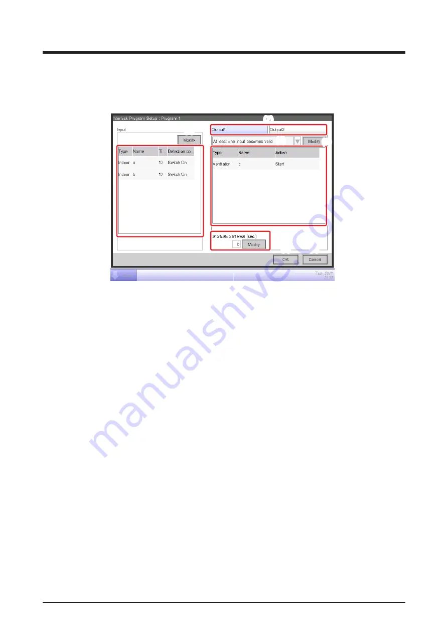
Interlock Program Setup Screen
This screen is displayed when you touch the Edit button on the main Interlocking Control screen.
Sets up details for the interlocking program.
(2)
(1)
(7)
(3)
(4)
(5)
(6)
(8)
(9)
(1)
Input
list
Displays the input conditions of the interlocking program
(2)
Modify
button (Input)
Displays the Interlock Program Input screen that allows you to set the input conditions for
interlocking.
(3)
Output
list
Displays the outputs of the interlocking program.
(4)
Input condition
combo box
Selects the input conditions for an interlocking program output.
Select an input condition from: Not detected, At least one input becomes valid, All inputs become
valid, At least one input becomes invalid, and All inputs become invalid.
(5)
Modify
button (Output)
Displays the Interlock Program Output Setup screen that allows you to set up the event to be
output by the interlocking program.
(6)
Sequential Start/Stop interval [sec.] field
Sets up the delay for the outputs. When sending a switch order to multiple management points,
you can set up an interval for outputting the orders.
Touch the Modify button and enter the time in the Numerical Input dialog that appears.
The range of values you can enter is 0 to 60, in increments of 1.
(7)
Output1/Output2
selection tab
Toggles between settings for Output1 and Output2. You can set up to two outputs to one
interlocking program.
(8)
OK
button
Saves the edit and closes the screen.
(9)
Cancel
button
Cancels the edit and closes the screen.
Summary of Contents for Intelligent Touch Manager DCM601A71
Page 309: ...EM11A017 1208 HT...


