background image


36 

Key 

Name 

Note 


In menu, click this key to page down.  


Long press this key to view zone alarm info.  


OK 

Click this key, you can


Enter sub menu  


Save setup. 


Restart keypad.  


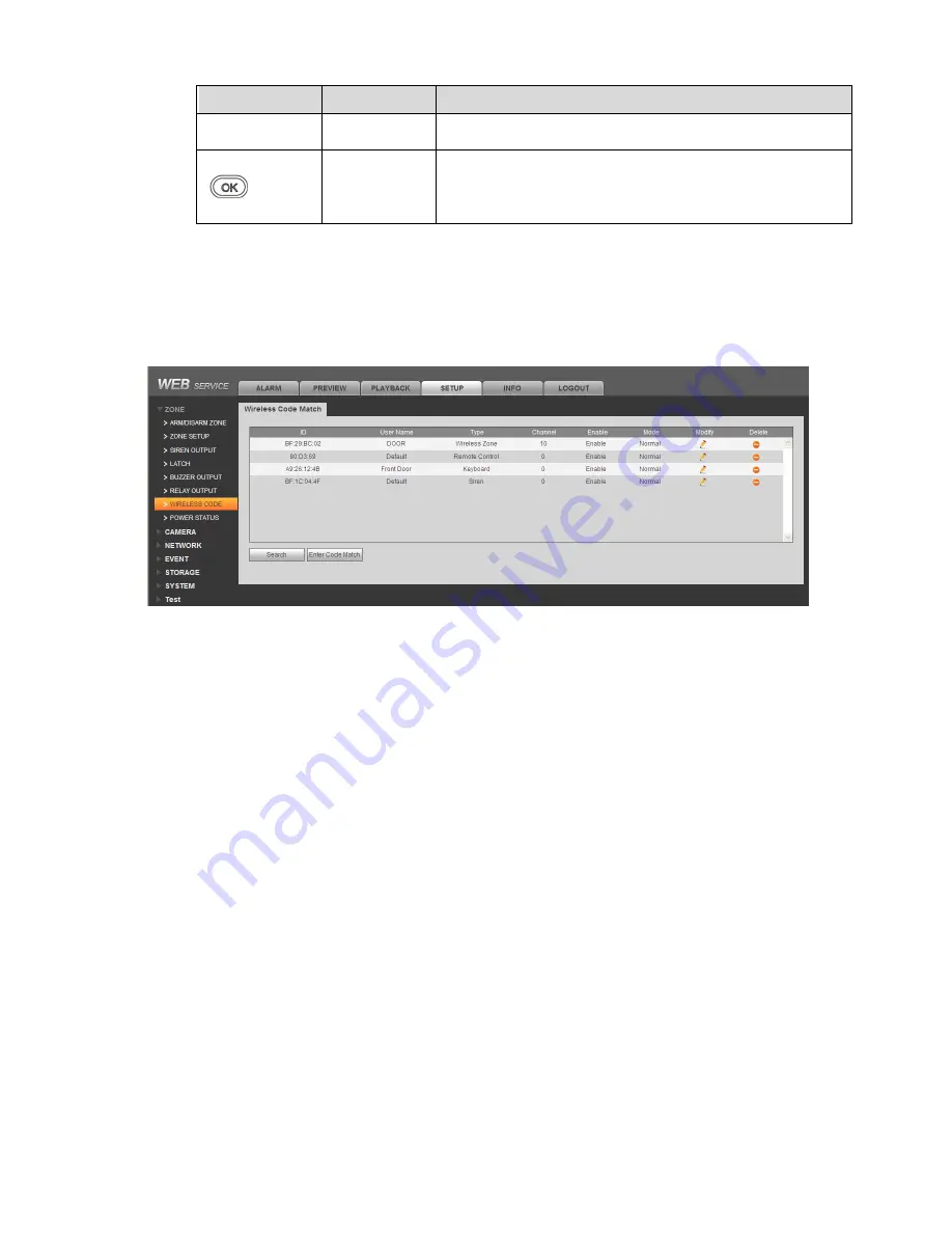
5.2 Wireless Match Code 

Before use, you must wireless match code with alarm controller. When successfully match code, 

you can set and arm/disarm.  

Step 1. In WEB Wireless Code interface, click Enter Code Match. See 

Figure 5-2


Figure 5-2


Step 2. Power up wireless alarm programming keypad, and select language.  

System shows it is matching code.  

Step 3. Click Return.  

If it shows matching is successful, then code match is complete. If it shows matching failed, 

then click return key to match again.  

Note: 

For already matched keypad, if you want to match to another controller, long press OK key to 

restart, and match code. 


5.3 Before Operation 

5.3.1 Notice 

Under  this environment,  alarm  keyboard is plugged  to power and  registration is 
successful,  enter  main interface.   
[Menu]+[Up/down  page sel[OK]+[Up/down  page sub 
sel[OK]+[Operation] 
 

Note: 
Different operations and methods refer to each chapter.  


5.3.2 Function Menu List 

Summary of Contents for ARC5408C-W

Page 1: ...Network Video Alarm Controller Quick Start Guide Version 1 0 0...

Page 2: ...8 4 3 Zone Config 19 4 4 Emergency Alarm Config 22 4 5 Siren and Alarm Output Config 23 4 6 Failure Config 25 4 7 Video Alarm Config 27 4 8 Event Report Config 29 4 9 Event Info View 31 4 10 Network C...

Page 3: ...o alarm controller This quick start guide will help you become familiar with our network video alarm controller in a very short time Before installation and operation please read the following safegua...

Page 4: ...ay from direct sunlight inflammable explosive substances and etc This series product shall be transported storage and used in the environment ranging from 10 to 55 6 Accessories Be sure to use all the...

Page 5: ...uarantee system long term stable operation The installation engineers are recommended to test the system regularly such as once a week Please arrange some training classes for the end user It is to ke...

Page 6: ...nd A V reuse 1 ch audio output and talk output reuse 8 ch wireless alarm programming keypad or 8 ch wires alarm programming keypad 16 wireless remote controls may use keypad remote control smart phone...

Page 7: ...2 Figure 1 1...

Page 8: ...2 Battery and HDD Installation To install battery Step 1 Tie the two lines symmetrically and pull through pedestal see Figure 2 2 Figure 2 2 Step 2 Place battery on the tied line Tie the battery tight...

Page 9: ...HDD fix it on pedestal with screwdriver Step 2 Insert HDD port on motherboard see Figure 2 4 Figure 2 4 2 1 4 Wall Mount The device supports wall mount and desktop placement To mount on wall Step 1 Op...

Page 10: ...istance of 184mm in between Insert the plastic expansion bolt and fasten self tapping screw Step 3 Hand the device on the screw Figure 2 5 2 2 ARC5408C Series 2 2 1 Appearance Video alarm controller a...

Page 11: ...he case position as in Figure 2 7 Figure 2 7 Step 2 Insert one end of battery line into battery and insert the other end of battery into external backup power port see Figure 2 8 Figure 2 8 2 2 3 Powe...

Page 12: ...nside controller and adaptor port faces power out hole on case Insert power line into power port on the controller see Figure 2 10 Figure 2 10 2 2 4 Install HDD To install HDD Step 1 Inside the contro...

Page 13: ...anti knock ring into the four slots of HDD bracket and HDD screw hole faces hole on bracket fasten anti knock ring screw see Figure 2 12 Figure 2 12 Step 3 Fix HDD with well installed bracket into the...

Page 14: ...ep 4 Insert one end of HDD line into hardware and insert the other end into HDD power port and data port on controller see Figure 2 14 Figure 2 14 2 2 5 Wall Mount The device supports wall mount and d...

Page 15: ...n bolt and fasten self tapping screw Step 3 Hand the device on the screw Figure 2 15 2 3 Wiring 2 3 1 Port Figure 2 16 No Name Note 1 Power port 14 5V power supply 2 Battery port Connect to 12V DC 7AH...

Page 16: ...10 GND Grounding 11 Audio input port 4 ch audio input 12 USB port Mouse 13 Alarm output port 1 ch relay output 14 Sensor port 3 ch sensor connection 15 RS485 port A1B1 to alarm programming keypad A2B...

Page 17: ...ange the lead acid battery AUX power supply output 1 and AUX power supply output 2 has voltage change range when not connecting to loading output 1 When main power supply is in place voltage is 14V no...

Page 18: ...re resistance is connection close to sensor end Before arming you must configure sensor type in zone setup as NO and NC see Ch 4 3 1 2 3 5 Alarm Output Wiring Alarm output wiring is shown in Figure 2...

Page 19: ...r are in the same network segment Please be aware that the initial IP of device is 192 168 1 108 When first login system shows control installation page you shall follow instructions to install contro...

Page 20: ...rm whether zone parameter is set correctly 4 Arm all once check whether zone is abnormal If there is abnormal you will see prompt as in Figure 4 1 Figure 4 1 Now you can manually check sensor and solv...

Page 21: ...r being armed internal track internal delay zone will auto be bypassed When users do not go out and expect no one is using the entrance you need the user to close all doors and windows before arming F...

Page 22: ...arm press Step 4 Input arm type no press key Note 1 Global arm 2 Instant arm 3 Out arm 4 Home Arm 5 Force to arm Step 5 Input main user password press key If successfully arm device buzzer has tone p...

Page 23: ...less remote control Alarm controller has tone prompt as successfully armed enter exit count down status according to set exit delay beep once every 1s and beep twice every 1s during the last 10s if fa...

Page 24: ...ol function report to platform Username Remote control name Delete wireless device Click and confirm delete the wireless remote control from system as you cannot arm disarm or alarm Add Wireless Remot...

Page 25: ...nagement Zone Setup See Figure 4 4 Figure 4 4 Step 1 Click See Figure 4 5 Figure 4 5 Parameter Note Enable alarm input Alarm input channel as zone no Alarm Name Customize zone name Zone Type Click set...

Page 26: ...nk siren buzzer no need to set Send alarm report to alarm center Not affected by arming disarming bypass Keypad will show this zone and send alarm prompt Emergency key 24 hour Mute Zone Device does no...

Page 27: ...erwise the system will link alarm Exit delay If exit delay time is set to 10s when a user arms within 10 trigger to zone is invalid Step 1 Select SETUP Zone Management Latch See Figure 4 6 Figure 4 6...

Page 28: ...r 3s buzzer will start to alarm device sends fire alarm info to alarm controller Duress In homepage input user 22 s password 123457 Robbery Long press SOS key for 3s Medical Emergency Long press 2 key...

Page 29: ...duration default is 5min Step 3 click OK 4 5 2 Relay Output Config Set relay output channel type and period Step 1 Select SETUP Zone Management Relay Output See Figure 4 9 Figure 4 9 Step 2 Select rep...

Page 30: ...ll disable Step 4 Click OK 4 5 3 Buzzer Output Config When alarm occurs enable buzzer during alarm time Step 1 Select SETUP Zone Management Buzzer Output See Figure 4 10 Figure 4 10 Step 2 Input buzze...

Page 31: ...No HDD When HDD has failure HDD indicator is ON HDD error Capacity warning Network Offline alarm When network has failure network indicator is ON See Figure 4 12 IP conflict MAC conflict Power Main po...

Page 32: ...alarm enabled the device will report the breaking event but does not affect use If you want to eliminate the circuit the zone can be isolated or two 2 2k resistor in series with the access zones Dete...

Page 33: ...red that is undefended areas Only fortified area mobile signal appears to be detected Record Channel When you select the desired video channels check an alarm occurs the system automatically starts t...

Page 34: ...ctors it cannot monitor the site Via setting tampering alarm we can prevent this situation Step 1 Select SETUP EVENT Tampering See Figure 4 16 Figure 4 16 Step 2 Select tab you want to configure See c...

Page 35: ...he next alarm event switches to the wired network Report mode Via report mode config you can select transmit event via Ethernet or telephone line Setup Note Not report Under this mode event will not b...

Page 36: ...f you want to view zone 11 20 alarm info please input 01 here so forth Zone 21 30 is 02 zone 31 40 is 03 When check box is empty the zone is normal When check box is black the zone is under alarm stat...

Page 37: ...al Transmission Mode Use default default is DTMF 5 S Dial Attempts If call center does not pick up call it will try this number of times range is 1 9 Dial Delay Time interval between two attempts User...

Page 38: ...controller ID Step 4 Click OK 4 10 3 P2P After P2P function is enabled open mobile client software directly input SN or scan the two dimension code save setup as you can arm disarm on client while ac...

Page 39: ...ve After setup is done status is online as P2P registration is successful When P2P registration is successful you can scan QR code via mobile phone or directly enter SN to add controller to access and...

Page 40: ...screen Note Valid in homepage only Home Arm This key is used to quickly arm at home After arming you can see S at the upper left corner on screen Note Valid in homepage only Disarm This key is used to...

Page 41: ...ming keypad and select language System shows it is matching code Step 3 Click Return If it shows matching is successful then code match is complete If it shows matching failed then click return key to...

Page 42: ...ing Controller is responding setup of wireless alarm programming keypad 5 3 4 User 5 3 4 1User Right Different user has different right see below User Type Code Default Password Right Note Administrat...

Page 43: ...thod Encode command OK Admin password Encode command is composed as follows 1 10 888888 No Note Encode address means the operation is to modify password default is 1 User encode range is 00 22 00 is a...

Page 44: ...quickly arm quickly arm at home General Arm Operation method arm type encode OK Admin password operator password Operation result If successfully arm controller will have tone prompt and enter exit de...

Page 45: ...ass isolation type code Zone number range is 001 256 Such as zone 1 number is 001 5 7 Zone Setup 5 7 1 Type Setup You can set zone parameter Operation method encode command OK Installer password Encod...

Page 46: ...command OK Installer password Encode command is composed as follows 1 0 001 01 No Note Zone no range is 001 256 Such as zone 1 no is 001 Link type 0 siren 1 alarm output 2 buzzer Link enable 0 not ena...

Page 47: ...o Note Code address means the operation is to set system tiime default is 1 Hour range is 0 23 Minute range is 0 59 Second range is 0 59 Note If you want to set date and time at the same time please f...

Page 48: ...password 1 0571888888886666 No Note Tel number composition 1 set first group phone number 2 set second group phone number Telephone number max of 16 digits of number 5 10 OutputSetup 5 10 1 Siren Outp...

Page 49: ...m Status 5 11 1 Zone You can search zone system status including zone no arm disarm status arm disarm bypass alarm status alarm non alarm zone type entry exit all day delay In delay display front time...

Page 50: ...mand to search RS485 address enter number 2 5 11 5 Host Status You can view each module status in alarm controller Operation method OK Result is shown below Note When check box is black it means corre...

Page 51: ...46 Alarm no range is 001 064...

Page 52: ...ome arm 601 Manual test 602 Period test 945 HDD capacity warning 946 HDD failure Note For detailed operation introduction please refer to our resource CD included in your package for electronic versio...

Reviews: