background image


S0707365
Page 4

Travel Motor (With Gearbox) (A6V160HD)


HYDRAULIC MOTOR OPERATION

1.     Hydraulic Motor operation.


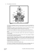
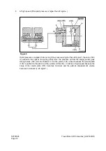
The high pressure oil from the hydraulic pump goes to the cylinder block (104) through the rear
flange (101) of the motor and the brake valve device and the timing plate (109). This high
pressure oil acts  only on the single side of the line Y1-Y2 which connects the bottom dead
center and the top dead center of the piston (105) stroke. The oil, after flowing into the side of
the cylinder block (104), exerts force on each piston (4 or S pieces) and generates force F (p kg/
cm x A cm


2


 ). The force F is exerted on the swash plate (103): as the swash plate (103) is tilted

with respect to the driving shaft (102) by a degrees, the force F is divided into two resultant
forces F2 and F3. Among these forces, radial force F3 develops torque T (F3 x ri) with respect
to each Yl-Y2 line. The combined torque T(Z(F3 x ri)), which is a rotation force, rotates the
cylinder block through pistons (105). The cylinder block is coupled with the driving shaft by a
spline, and the driving torque is transferred to the shaft.

Figure 2 

Summary of Contents for Solar 420LC-V

Page 1: ...Return to Master Table of Contents 1HYDRAULICS...

Page 2: ...afety recommendations and safe shop practices outlined in the front of this manual or those contained within this section Always use tools and equipment that is in good working order Use lifting and h...

Page 3: ...t 8 Swing Operating Circuit 8 Right Swing Operating Circuit 9 Left Swing Operating Circuit 9 Swing Relief Valve and Make up Valve 9 Travel Operating Circuit 9 Forward Travel Circuit 10 Reverse Travel...

Page 4: ...nd Flow Meter Kit Installation and Testing 20 Swing System Troubleshooting 22 Precautions Initial Checks 22 Swing Relief Valve Checking and Adjustment 22 Troubleshooting Swing Gearbox 24 Troubleshooti...

Page 5: ...zation system which allows the operator to choose between three distinctly different power modes high output rapid cycling maximum speed power mode low fuel consumption low noise light duty power mode...

Page 6: ...vailable circuit for these functions the output of both pumps can be combined allowing higher speed operation Boom up arm crowd and dumping functions can operate in any one of the two available power...

Page 7: ...me of oil going to the cylinder will not exceed the volume of oil coming out BOOM UP CIRCUIT When you pull the boom control lever backward the right side pilot valve generates secondary boom up pilot...

Page 8: ...valve generates secondary pressure that is transmitted to the ARM1 and ARM2 of the control valve simultaneously When secondary pilot pressure reaches 7 10 kg cm2 100 142 psi the arm control valve spoo...

Page 9: ...ET and BC spools open so that oil from both pumps goes to the bucket cylinder BUCKET DUMP CIRCUIT When the bucket control lever is put in the dump mode the right side pilot valve generates secondary b...

Page 10: ...ing swing operation the possibility exists that surge pressure in the circuit caused by inertial momentum of the upper works and correspondingly reduced pressure at the opposite motor port could produ...

Page 11: ...each side of the machine REVERSE TRAVEL CIRCUIT When the right and left travel control levers are pushed backward output from both main pumps is directed through the TRAVEL R and TRAVEL L spools on t...

Page 12: ...r are available at the pump drive flex coupling pull out the electrical tray under the operator s seat to inspect the self diagnostic display If the EPOS trouble code display is clear check hydraulic...

Page 13: ...s outside the tolerance specified in the table adjust gear pump relief pressure by loosening the lock nut and turning the set screw in clockwise to increase pressure or turning it out to decrease it N...

Page 14: ...electrical lead Vent the lever on top of the hydraulic tank to relieve pressure and connect an in line t style adapter to the valve pressure port Install a 60 bar 870 psi 1 000 psi test gauge in the a...

Page 15: ...ny tests NOTE Vent air from the hydraulic system before installing test equipment Use the lever on the reservoir while the engine is running Pour clean replacement fluid back into the system if excess...

Page 16: ...ckwise to decrease it Pressure must be 350 bars 5075 psi or up to 10 bars 145 psi higher Because one adjustment can affect the other check low stage main relief pressure by repeating the cylinder stal...

Page 17: ...Table of Contents NOTE The electrical pressure up power boost solenoid valve located alongside the swing priority solenoid and arm speed control solenoid in compartment rear of the operator s cab must...

Page 18: ...being consistently overloaded and engine troubleshooting shows engine performance to be at or above rated output If reduced cylinder speed and diminished work performance provide an indication that ra...

Page 19: ...e of the adjustment procedures could affect the setting of the others Check and record the arm dump speed performance test before and after input power adjustment whether or not a flow meter is used N...

Page 20: ...crew 2 the square tipped adjusting screw should be turned in the opposite direction turns to avoid changing inner spring adjustment Pump input power adjustments are normally made in small increments 1...

Page 21: ...ropriate fittings and adapter flanges to guarantee a pressure tight seal NOTE Be sure to maintain even tightening torque on all flange fittings Use Loctite brand PST 545 or an alternate manufacturer s...

Page 22: ...ion of this book If test results do not measure up to specified values pump output tests can be repeated using different control levers Recheck front pump operation while stroking the bucket cylinder...

Page 23: ...to check the engine Investigate unusual operating noises or vibration Check for loose bolts connections SWING RELIEF VALVE CHECKING AND ADJUSTMENT Make a check of operating pressures through the swin...

Page 24: ...d cabin When pressure through the port is at the recommended level the brake release valve should disengage the swing brake allowing the swing motor to rotate the excavator If pressure adjustment to t...

Page 25: ...ble and repair Pilot control pressure low or swing control valve stuck Disassemble Repair pilot pressure swing spool 305 and or swing control valve Swing motor defective Test motor drain rate Replace...

Page 26: ...ises from the swing motor Hydraulic pump or valve problem Troubleshoot hydraulic system Oil Leakage From drive shaft From bolted connections or other assembled surfaces Oil seal damaged Assembly compo...

Page 27: ...oad relief valve malfunction Readjust or replace Oil leak at make up valve Clean repair Control valve spool damaged Repair or replace Dirt in control valve spool Clean or replace Actuator joystick foo...

Page 28: ...Particulate contamination Disassemble clean main poppet Broken or damaged spring Replace Adjusting screw loose Readjust Main poppet sticking Repair replace Clogged orifice in pilot passage to control...

Page 29: ...adjust Components worn out past wear limits Replace Problem Possible Causes Remedies Secondary pressure does not increase Low primary pressure Check primary pressure Broken spring Replace spring Spool...

Page 30: ...handle subassembly Secondary pressure too high Dirt other interference between valve parts Clean repair or replace Return line pressure too high Redirect return line Secondary pressure does not hold s...

Page 31: ...Page 30 Hydraulic System Troubleshooting Testing and Adjustment Return to Master Table of Contents...

Page 32: ...ways use tools and equipment that is in good working order Use lifting and hoisting equipment capable of safely handling load Remember that ultimately safety is your own personal responsibility MODEL...

Page 33: ...S0703010K Page 2 Accumulator TABLE OF CONTENTS General Description 3 Specifications 4...

Page 34: ...and out and an elastic diaphragm to separate the two chambers The flexible diaphragm changes shape to conform to the changing pressures and volumes of the two fluids in the upper and lower chambers T...

Page 35: ...r s data label Repeat this test at least once a year to verify proper functioning of the accumulator 3 As hydraulic system pressure overcomes accumulator pre charge pressure the flexible diaphragm beg...

Page 36: ...lined in the front of this manual or those contained within this section Always use tools and equipment that is in good working order Use lifting and hoisting equipment capable of safely handling load...

Page 37: ...S0704090K Page 2 Center Joint Swivel TABLE OF CONTENTS General Description 3 Parts List 4 Troubleshooting Testing and Adjustment 5 Inspection 5 Testing 5 Disassembly 6 Reassembly 6...

Page 38: ...RIPTION The center joint swivel is designed to allow hydraulic oil from the upper structure to flow to components in the lower structure It is capable of allowing continuous 360 rotation of the upper...

Page 39: ...PARTS LIST Figure 1 Reference Number Description 10A Center Joint Body 10B Spindle 10C O ring 10D Slipper Seal 10E O ring 10F Cover 10G Hex Bolt 10H Spring Washer 10I Plug 10J Plug 25 Spring Washer 3...

Page 40: ...s of the excavator A high pressure relief valve with a setting pressure 1 5 times maximum system pressure A stop valve A manually operated in line change over valve Install the change over valve upstr...

Page 41: ...the body of the Center Joint 7 Before reassembling the center swivel visually inspect ball bearing surfaces for visible signs of wear damage or discoloration and replace any worn component Check clea...

Page 42: ...ing the cover bolts 5 Pre fill the center swivel with clean hydraulic fluid prior to reassembly of high pressure and drain line piping Clean and pre fill piping line ends to reduce the amount of air i...

Page 43: ...S0704090K Page 8 Center Joint Swivel...

Page 44: ...y handling load Remember that ultimately safety is your own personal responsibility MODEL SERIAL NUMBER RANGE Solar 130LC V 0001 and Up Solar 130W V 0001 and Up Solar 170LC V 1001 and Up Solar 170W V...

Page 45: ...age 2 Cylinders Return to Master Table of Contents TABLE OF CONTENTS General Description 3 Theory of Operation 3 Parts List 4 Special Tools and Materials 6 Piston Nut 6 Piston Jig 8 Disassembly 10 Rea...

Page 46: ...e of the cylinder shown as oil path A or to the front of the cylinder oil path B The cylinder rod is extended as oil flow is pumped through the circuit to the back side of the piston The force F1 of t...

Page 47: ...roke length than it does to lengthen it Q1 Q2 PARTS LIST The following parts list is a partial listing only for full and complete parts list information refer to the Hydraulic Equipment Component Part...

Page 48: ...Rod Bushing 7 Bolt 8 Retaining Ring 9 Rod Cover 10 O ring 11 O ring 12 Backup Ring 13 Piston Rod 14 Cylinder Tube 15 Cushion Ring 16 Piston 17 Slide Ring 18 Wear Ring 19 Slipper Seal 20 O ring 21 Back...

Page 49: ...000 Page 6 Cylinders Return to Master Table of Contents SPECIAL TOOLS AND MATERIALS PISTON NUT G A B C D R R15 R20 F C3 C5 E HBOJ040I Figure 6 Material SM45C AISI 1045 Rockwell Harden from 22 27 Oil Q...

Page 50: ...350 0 mm 13 78 in 15 0 mm 0 59 in S170LC V ARM S200W V ARM S250LC V BOOM ARM BUCKET S290LC V BOOM BUCKET 125 0 mm 4 92 in 102 0 mm 4 02 in 11 0 mm 0 43 in 4 5 mm 0 18 in 35 0 mm 1 38 in 350 0 mm 13 7...

Page 51: ...S0705000 Page 8 Cylinders Return to Master Table of Contents PISTON JIG 2 B A C E D R R15 20 F R F 2 I H G HBOJ050I Figure 7 Material SM45C AISI 1045 Rockwell Harden from 22 27 Oil Quence...

Page 52: ...m 0 59 in 12 0 mm 0 47 in S130W V BUCKET S220LC V ARM 110 0 mm 4 33 in 14 0 mm 0 55 in 17 0 mm 0 67 in 40 0 mm 1 57 in 75 0 mm 2 95 in 32 0 mm 1 26 in 350 0 mm 13 78 in 15 0 mm 0 59 in 15 0 mm 0 59 in...

Page 53: ...NOTE Wrap a cloth or other protective material around piston rod to avoid possibility of accidentally scratching or scoring rod surface while fasteners are being loosened and removed Component parts n...

Page 54: ...tween cover and end of cylinder wall before using a plastic or other soft faced hammer for final disassembly 5 Begin withdrawing piston rod assembly away from cylinder Attach a lifting support when fi...

Page 55: ...metallic support through end of rod 8 Loosen set screw by using a socket wrench 9 Fabricate or purchase a piston nut removal wrench Dimensions are called off at beginning of this procedure This tool...

Page 56: ...e piston Detach cushion ring 15 taking care not to damage cushion ring 11 Use a plastic hammer to evenly pull off rod cover 9 from end of piston rod Be careful not to damage rod bushing 6 and dust wip...

Page 57: ...te width tip to facilitate removal of slipper seal 19 wear ring 18 and slide ring 17 from piston 16 14 Pull off O ring 20 and backup ring 21 from cylinder head 15 During disassembly of cylinder head b...

Page 58: ...e 15 Cylinders Return to Master Table of Contents 16 Disassemble retaining ring 3 and dust wiper 2 Separate retaining ring 8 and rod bushing 6 17 Force out pin bushing 1 from body of cylinder Figure 2...

Page 59: ...f rod cover components install the dust wiper 2 and rod bushing 6 to the rod cover 9 Insert retaining rings 3 and 8 IMPORTANT Replace any part that shows evidence of damage or excessive wear Replaceme...

Page 60: ...l jig third item in list of specialized tools at the beginning of this procedure to attach seal Cool seal by pushing a retracting jig against seal for several minutes Apply a strip of clean see throug...

Page 61: ...on assembly to piston rod 7 Use specially fabricate or factory sourced tool to tighten piston nut 22 8 Assemble wear ring 18 slide ring 17 and set screw 23 to piston assembly 9 Immobilize body of cyli...

Page 62: ...ng compound Loctite 242 or 243 or an alternate manufacturer s equivalent product to all end cover retaining bolts Wrap a protective cushion around end of rod while tightening fasteners to prevent poss...

Page 63: ...S0705000 Page 20 Cylinders Return to Master Table of Contents...

Page 64: ...tained within this section Always use tools and equipment that is in good working order Use lifting and hoisting equipment capable of safely handling load Remember that ultimately safety is your own p...

Page 65: ...l Description 3 Theory of Operation 3 Swing Motor Anti cavitation Make up Valve 4 Relief Valve 5 Swing Brake Operation 5 Parts List 8 Specifications 10 Special Tools 11 Disassembly 12 Cleaning and Ins...

Page 66: ...e swash plate Item 3 to generate oil flow through the motor while force F2 pushes laterally at a right angle against the drive shaft providing the rotational energy to turn the cylinder block around t...

Page 67: ...d while current flow is reduced shifting the spool in the priority valve for increased oil flow to the boom arm side of the circuit SWING MOTOR ANTI CAVITATION MAKE UP VALVE Unlike those designs for h...

Page 68: ...nst spring pressure inside the valve opening the relief valve until pressure at the spring chamber g momentarily reduces g chamber pressure Pg Pg subsequently increases until the piston reaches the en...

Page 69: ...iston the friction plate and swing motor casing are separated releasing the brake IMPORTANT Along with the swing brake a 2 position positive swing lock has also been provided It should be secured when...

Page 70: ...S0707260 Page 7 Swing Motor...

Page 71: ...LIST 303 468 487 51 116 111 121 122 123 124 117 113 101 401 472 712 707 131 451 464 485 993 432 106 443 304 471 437 106 432 491 301 438 106 114 118 743 743 742 742 743 706 702 433 351 444 469 488 355...

Page 72: ...ly 121 Piston 122 Shoe 123 Retainer 124 Shoe Plate 131 Valve Plate 301 Casing 303 Valve Casing 304 Front Cover 351 Plunger 355 Spring 401 Socket Bolt 432 Snap Ring 433 Snap Ring 437 Snap Ring 438 Snap...

Page 73: ...on Displacement 121 6 cc rev 18 85 in3 rev 128 0 cc rev 7 81 in3 rev Crossover Relief Valve Setting 280 kg cm2 3 980 psi 280 kg cm2 3 980 psi Maximum Supply Flow Rate 2000 rpm 227 lpm 60 gpm 210 lpm 5...

Page 74: ...S0707260 Page 11 Swing Motor SPECIAL TOOLS Figure 5...

Page 75: ...nds and clothing promptly and don t allow used oil containers to accumulate 3 After oil has been drained completely motor should be positioned so that exposed end of drive shaft faces downwards IMPORT...

Page 76: ...ing 303 5 Disassemble brake valve 31 from side of casing 6 Loosen and remove relief valve assemblies 51 from upper valve casing 303 7 Remove RO plug 469 from upper valve casing 303 That will allow sub...

Page 77: ...after cover is removed 9 Remove all twenty brake springs NOTE If brake springs are to be reused and not replaced check and record spring free height If a test stand is available check height of all t...

Page 78: ...ded incrementally by maintaining previous wear pattern relationships by avoiding new ones 12 Pull out friction plates 742 and separator plates 743 from area behind cylinder block 13 Remove lock ring 4...

Page 79: ...of casing 16 Disassembly of motor has now been completed unless there is any reason to suppose that drive shaft bearing has become excessively worn If it is necessary replace bearing by pulling away s...

Page 80: ...parated during removal Apply force 2 Figure 21 and use a plug 1 to hammer through drive shaft opening in cover B If upper bearing is going to be replaced whether as a general precaution as part of nor...

Page 81: ...ssemble relief valves pull out plug 201 Figure 4 disassemble bushing 343 spring 322 and spring seat 331 from rod 303 Position valve housing facing down and separate piston 302 rod 303 spring 321 sprin...

Page 82: ...ded unless motor has had minimal use Inspect O rings and oil seals very carefully for cuts nicks brittleness or softness or any other type of damage or distortion before final reassembly NOTE When par...

Page 83: ...bly if any must be reused Item Standard Value mm In Replacement Limit mm In Remedy Clearance between cylinder bore and piston D d 0 028 mm 0 0011 in 0 058 mm 0 0023 in Replace piston or cylinder Clear...

Page 84: ...re not disassembled go onto next phase of assembly Bearing reassembly begins with replacement of stop ring 432 Figure 4 and its accompanying Parts List and spacer 106 on drive shaft 101 Make sure that...

Page 85: ...oil seal Be careful that you install seal inside cover with correct side facing in 5 Before replacing O ring 471 in lower casing 301 grease O ring and or inside of groove very lightly to facilitate as...

Page 86: ...g grease on assembled side can help keep individual components in place 9 Carefully examine cylinder block for any evidence of damage around rotating parts Put push rods 116 and front spacer 117 back...

Page 87: ...3 and two friction plates 742 which should be positioned as shown in drawing below with clearance towards side of casing with brake valve 1 Figure 38 13 Very lightly grease larger O rings 706 and 707...

Page 88: ...re 43 of the valve plate turned away from mounting flanges 1 on side of valve plate Lightly grease O ring to help keep it in place during assembly 18 Bolt up two halves of motor casing 301 and 303 Fig...

Page 89: ...by putting rod spring stop and piston back together then turning plunger side of valve up to reassemble valve body and all components of piston spring seat spring bushing retainer O ring and plug 21...

Page 90: ...S0707260 Page 27 Swing Motor 22 Replace the VP plugs 464 468 and O rings 485 487 on each of the three plugs Reinstall the brake cutoff valve 31 Figure 49...

Page 91: ...S0707260 Page 28 Swing Motor...

Page 92: ...practices outlined in the front of this manual or those contained within this section Always use tools and equipment that is in good working order Use lifting and hoisting equipment capable of safely...

Page 93: ...nd Component Groups 19 Sealing Drive Shaft 22 Sealing Control Parts 23 Sealing Relief Valve 24 Disassembly Port Plate 24 Exchanging Rotary Group 29 Travel Motor Speed Reduction Gearbox Disassembly 32...

Page 94: ...section at the end Travel motor consists of the hydraulic motor and reduction gearbox Hydraulic motor consists of the rotary part cross relief valve negative brake counter balance valve and tilting pa...

Page 95: ...er flowing into the side of the cylinder block 104 exerts force on each piston 4 or S pieces and generates force F p kg cm x A cm2 The force F is exerted on the swash plate 103 as the swash plate 103...

Page 96: ...D at the return side of the motor and part B at the tank are connected together by a hole in the spool and the motor turns as the return oil from motor flows into the tank By the movement of spool 126...

Page 97: ...lic motor stops because all passages are closed completely Like this the spool s returning speed controls the return oil from motor gradually according to the spool s shape and stops the hydraulic mot...

Page 98: ...ses above 11 kg cm2 it over comes the spring force and the piston 112 moves By the movement of the piston the force exerted by the piston 112 on the separator plate 116 and the friction plate 115 is r...

Page 99: ...112 returns by the spring 113 force If the piston 112 is pushed by the spring force the separator plate 116 and the friction plate 115 are pushed to the spindle of the reduction device The friction f...

Page 100: ...ed from port A If the pressure is lower than 10 kg cm2 the valve 163 is pushed to the left by the spring I66 force the pressure oil from the supply port B is blocked and the oil of the chamber C flows...

Page 101: ...alve 163 is pushed to the right bv the spring 166 force the pressure oil from the supply port B goes through valve 163 into the chamber C So the piston 161 is fixed because the swash plate 103 is push...

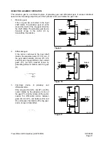
Page 102: ...erential gear If the carrier combined to the input shaft rotates the planetary gears Pl P2 turn If the gear ratios between R and P1 Pl and P2 are properly different the co axial gears P1 and P2 transm...

Page 103: ...S0707365 Page 12 Travel Motor With Gearbox A6V160HD PARTS LIST Travel Motor Figure 12 HTS6331...

Page 104: ...eference Number Description Qty 6315 Travel Motor 2 1 Rotary Group 1 2 Control 1 5 Housing 1 9 Retaining Ring 1 10 Shaft Seal Ring 1 11 Back Up Plate 1 12 O ring 1 13 Rocking Screw 1 17 Threaded Pin 2...

Page 105: ...S0707365 Page 14 Travel Motor With Gearbox A6V160HD Travel Motor Rotary Group Figure 13 HTS6321...

Page 106: ...1 1a Cylinder 1 1b Control Lens 1 1c Center Pin 1 1d Piston 7 1e Steel Sealing Ring 14 1f Adjustment Shim 1 1g Pressure Spring 1 1h Retaining Plate 1 1i Screw 14 2 Drive Shaft 1 3 Shim 1 6 Back Up Pl...

Page 107: ...S0707365 Page 16 Travel Motor With Gearbox A6V160HD Travel Motor Control HTS6331 Figure 14...

Page 108: ...on 1 4 Control Bush 1 5 Control Piston 1 6 Pressure Spring 1 7 Rocking Screw 1 8 Throttle Screw 1 9 Throttle Screw 1 13 Rocking Screw 1 14 Valve Screw 1 15 Bush 1 20 Socket Head Screw 2 21 Socket Head...

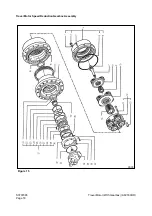
Page 109: ...S0707365 Page 18 Travel Motor With Gearbox A6V160HD Travel Motor Speed Reduction Gearbox Assembly 3033 Figure 15...

Page 110: ...ss y 1 11 Screw Uni 5931 4 12 3rd Red Gear Ass y 1 13 Bushing 4 14 Sun Gear 1 15 Bearing Ass y 1 16 Gasket Lifetime 1 17 Hub 1 18 Spacer 1 19 Brake Shaft 1 20 O ring 1 21 Disc 7 22 Ring Steel 6 23 Rin...

Page 111: ...CBV Brake Release Valve Relief Valves Incooporated 2 Beginning of Regulation At Max Displacement 3 2 hole Flange 4 Drive Shaft 45 mm Diameter 5 Viton Seals 6 Alternating Direction of Rotation 7 Series...

Page 112: ...s and head support surface dimensions in accordance with DIN 912 DIN 931 and DIN 933 These values are also valid only for light or unoiled untreated surface and for use only with torque indicating wre...

Page 113: ...200 300 Tightening torques for seal lock nuts Metric ISO Standard Thread The values for tightening torques shown in the table are valid only for seal lock nuts of the strength class 8 8 and with metri...

Page 114: ...S0707365 Page 23 Travel Motor With Gearbox A6V160HD TRAVEL MOTOR DISASSEMBLY SECTIONAL VIEW HTS063S Figure 16...

Page 115: ...epair work at hydraulic aggregates 1 Close all points of the hydaulic aggregates 2 Replace all seals NOTE Use only original Hydromatik spare parts 3 Check all seal and sliding surfaces for w ear NOTE...

Page 116: ...Motor With Gearbox A6V160HD 4 Full up hydaulic aggregates with hydraulic oil before start up 5 Seal kit for drive shaft 6 External seal kit 7 Housing Figure 21 HTS005S Figure 22 HTS006S Figure 23 HTS...

Page 117: ...Complete rotary group 9 Port plate with control piston and counter balance valve 10 Relief valve Make up check valve 11 Replace seal nut NOTE First measure and record setting height Figure 25 HTS009S...

Page 118: ...With Gearbox A6V160HD 12 When tightening counter hold setting screw then check setting height SEALING DRIVE SHAFT 1 Protecting the drive shaft 2 Remove retaining ring and shim Figure 29 HTS013S HTS014...

Page 119: ...pliers 5 Press in shaft seal and shim with bush to stop NOTE Pay attention to pressing depth Mark for pressing depth Assemble retaining ring SEALING CONTROL PARTS 1 H Z Controler NOTE Inspect O ring O...

Page 120: ...S0707365 Page 29 Travel Motor With Gearbox A6V160HD 2 Inspect O ring DISASSEMBLY PORT PLATE 1 Note dimension X 2 Remove Qmin screw Figure 36 HTS021S Figure 37 HTS023S...

Page 121: ...iston rings to hang out the cylinder boring Swivel rotary group to zero position with screw Q max 5 Port plate A Mark position B Loosen screws C Remove 6 Ceck O ring NOTE Coat new O ring with some gre...

Page 122: ...S0707365 Page 31 Travel Motor With Gearbox A6V160HD 7 Braking valve 8 Throttle pin 9 Valve 10 Pressure control valve HTS027S Figure 41 HTS028S Figure 42 HTS029S Figure 43 HTS030S Figure 44...

Page 123: ...S0707365 Page 32 Travel Motor With Gearbox A6V160HD 11 Pressure relief valve 12 Positioning piston 13 H Z control 14 Check valve HTS031S Figure 45 HTS032S Figure 46 HTS033S Figure 47 HTS034S Figure 48...

Page 124: ...S0707365 Page 33 Travel Motor With Gearbox A6V160HD 15 Screw in threaded pin into center pin 16 Fix the cylinder with disc and locknut HTS035S Figure 49 HTS036S Figure 50 HTS037S Figure 51...

Page 125: ...n the drive shaft EXCHANGING ROTARY GROUP 1 Complete rotary group NOTE Setting of hydraulic part necessary 2 Rotary group Mechanical part Adjust drive shaft with bearing Hydraulic part Adjustment nece...

Page 126: ...ining plate NOTE screws are glued Use Torx tools 6 Free of corrosion erosion or fretting No damage to splines or keyways 7 Pistons No scoring and no pittings 8 Center pin No scoring and no pittings HT...

Page 127: ...ontrol lens Bores free of scoring no evidence of wear Faces smooth and even free of cracks and scoring 11 Control housing Sliding surface and side guides free of scoring and no wear 12 Visual check Be...

Page 128: ...REDUCTION GEARBOX DISASSEMBLY 1 Drain gear oil and remove travel motor and O ring 2 Remove motor flange 8 socket bolts M16 x 35 Figure 64 3 Remove O ring from motor flange Figure 65 4 Remove O ring f...

Page 129: ...ox A6V160HD 5 Attach disc B Figure 67 to spring retainer fasten pusher A to hub and install screw rod C 6 Remove circlip from hub groove using pliers Figure 68 7 Remove jig and circlip Figure 69 Figur...

Page 130: ...60HD 8 Remove spring retainer Figure 70 9 Pull spring from groove Figure 71 10 Blow air into brake port hole and remove brake piston using pliers Figure 72 11 Remove brake shaft Figure 73 Figure 70 30...

Page 131: ...D 12 Remove disc Figure 74 13 Remove O ring and backup ring Figure 75 14 Turn reduction gear assembly over and remove 2 plugs M22 x 1 5 Figure 76 15 Remove 16 socket bolts M14 x 40 Figure 77 Figure 74...

Page 132: ...6V160HD 16 Remove end cover using puller Figure 78 17 Remove O ring from end cover groove Figure 79 18 Remove first sun gear Figure 80 19 Remove first planetary gear assembly Figure 81 Figure 78 3048...

Page 133: ...Remove second sun gear Figure 82 21 Remove second planetary gear assembly Figure 83 22 Remove third sun gear Figure 84 23 Loosen bolts 4 M 30 x 150 from third planetary gear assembly Figure 85 Figure...

Page 134: ...6V160HD 24 Remove bolts Figure 86 25 Seperate hub from reduction gear housing using press and stopper Figure 87 NOTE Do not remove main ball bearing 26 Remove third shift assembly from hub Figure 88 F...

Page 135: ...07365 Page 44 Travel Motor With Gearbox A6V160HD 27 Remove bushing from hub using a jig Figure 89 28 Remove bearing inner race and spacer from hub using puller Figure 90 H H Figure 89 3059 Figure 90 3...

Page 136: ...S0707365 Page 45 Travel Motor With Gearbox A6V160HD 29 Remove gasket Figure 91 Figure 91 3061...

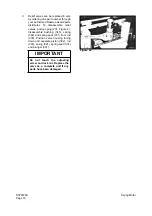
Page 137: ...pection procedures refer to General Maintenance Procedures section Gearbox Inspection 1 If a gear is damaged replace the damaged gear and the interlocking gear next to it If one planetary gear is dama...
Page 138: ...tor With Gearbox A6V160HD TRAVEL MOTOR SPEED REDUCTION GEARBOX REASSEMBLY 1 Install seal to jig Figure 92 2 Install jig to housing Figure 93 3 Clean seal surface Figure 94 HTS3062S Figure 92 3062 Figu...
Page 139: ...ly lubricant to seal surface Figure 96 6 Support ball bearing housing with spacers 1 and 2 Figure 97 and install bearing into housing Install spacer between balls noting diameter shown in illustration...

Page 140: ...nstall hub to housing Figure 99 9 Press hub into housing using a press and a stopper Figure 100 10 Install four bushings using a press Figure 101 11 Assemble planetary gear assembly Figure 102 Figure...

Page 141: ...assemblies using press Figure 103 13 Tighten gear box of planetary gear assembly to 150 Nm 110 7 ft lb Figure 104 14 Assemble third shift sun gear Figure 105 15 Assemble the second shift reduction as...

Page 142: ...r carrier into hub Figure 108 18 Apply loctite to planetary gear carrier fastening bolts 19 Install and tighten bolts Figure 109 NOTE In next step the O ring and backup rings are different Be careful...

Page 143: ...te 243 to bolts and torque to 10 Nm 7 38 ft lb Figure 111 22 Tighten plugs to 6 8 Nm 4 42 5 90 ft lb Figure 112 23 Turn housing over and install second shift sun gear Figure 113 24 Install first shift...

Page 144: ...Gearbox A6V160HD 25 Install first shift sun gear Figure 115 26 Install O ring 1 Figure 116 and backup ring 2 into hub groove NOTE The O ring and backup rings are different Be careful not to switch th...

Page 145: ...bly Figure 117 28 Install brake disc assembly starting with a copper disc seven pieces and alternating with steel discs six pieces Figure 118 and Figure 119 29 Install jig to hub and insert spring ret...

Page 146: ...using circlip pliers Figure 121 31 Install O ring to hub groove Figure 122 32 Place brake piston inside hub being careful not to damage seal Figure 123 33 Insert springs into brake piston holes Figur...

Page 147: ...6 Travel Motor With Gearbox A6V160HD 34 Install retainer disc Figure 125 35 Install O ring to motor flange groove Figure 126 36 Tighten motor flange to hub Figure 127 Figure 125 3095 Figure 126 3096 F...

Page 148: ...With Gearbox A6V160HD TRAVEL MOTOR REASSEMBLY ROTARY GROUP ASSEMBLY 1 Rotary group completely assembled ready for assembly 2 Place assembly sleeve 3 Warm up housing to 80 C 176 F Figure 128 HTS051S F...

Page 149: ...sing to seat position 5 Fix zero position of cylinder with Qmax screw 6 Disassemble cylinder fixing screw 7 Insert O ring ROTARY GROUP ADJUSTMENT SEE SERVE INFORMATION 1 Determine cylinder swivel rang...

Page 150: ...0707365 Page 59 Travel Motor With Gearbox A6V160HD 2 Disc 3 Place centering disc 4 Mount measuring device 5 Check dimention X HTS056S Figure 134 HTS057S Figure 135 HTS058S Figure 136 HTS059S Figure 13...

Page 151: ...order 3 Mount port plate 4 Assemble port plate NOTE Take care of assembly design Tighten fixing screws with torque 5 Set Qmin screw to dimention 6 Assemble plug 7 Remove assembly sleeve 8 Assemble sh...

Reviews: