S0707260
Page 25
Swing Motor
15.
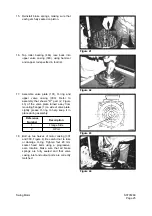
Reinstall brake springs, making sure that
each gets fully seated on piston.
16.
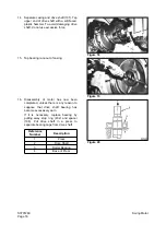
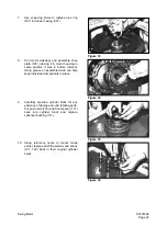
Tap roller bearing (444) race back into
upper valve casing (303), using hammer
and copper rod specified in tool list.
17.
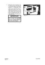
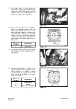
Assemble valve plate (131), O-ring and
upper valve casing (303). Refer to
assembly that shows "R" part (2, Figure
43) of the valve plate turned away from
mounting flanges (1) on side of valve plate.
Lightly grease O-ring to help keep it in
place during assembly.
18.
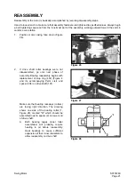
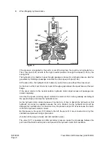
Bolt up two halves of motor casing (301
and 303, Figure 4). Be careful not to lose
or damage O-ring. Tighten four 20 mm
socket head bolts using a progressive,
even rotation. Make sure that all brake
springs are fully seated and that valve
casing inlet and output ports are correctly
matched.
Reference
Number
Description
1
Flange Side
2
R Port
Figure 41
Figure 42
Figure 43
Figure 44
Summary of Contents for Solar 420LC-V
Page 1: ...Return to Master Table of Contents 1HYDRAULICS...
Page 33: ...S0703010K Page 2 Accumulator TABLE OF CONTENTS General Description 3 Specifications 4...
Page 43: ...S0704090K Page 8 Center Joint Swivel...
Page 63: ...S0705000 Page 20 Cylinders Return to Master Table of Contents...
Page 70: ...S0707260 Page 7 Swing Motor...
Page 74: ...S0707260 Page 11 Swing Motor SPECIAL TOOLS Figure 5...
Page 91: ...S0707260 Page 28 Swing Motor...
Page 103: ...S0707365 Page 12 Travel Motor With Gearbox A6V160HD PARTS LIST Travel Motor Figure 12 HTS6331...
Page 107: ...S0707365 Page 16 Travel Motor With Gearbox A6V160HD Travel Motor Control HTS6331 Figure 14...
Page 136: ...S0707365 Page 45 Travel Motor With Gearbox A6V160HD 29 Remove gasket Figure 91 Figure 91 3061...


