S0703010K
Page 4
Accumulator
NOTE:
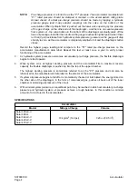
Pre-charge pressure is referred to as the "P1" pressure. The accumulator manufacturer’s
"P1" rated pressure should be stamped or marked on the accumulator’s rating plate.
Annual checks of actual pre-charge pressure should be made by tapping a hydraulic
pressure gauge (and 3-way adapter coupling) into the valve on the bottom of the
accumulator. When hydraulic fluid is pushed out the lower valve opening by the pressure
of the gas charge on the other side of the diaphragm - and there is no counter-pressure
from system oil - the valve button on the bottom of the diaphragm eventually seals off the
lower oil passage. Just after the needle on the gauge reaches its highest point (when there
is 0 bar (0 psi) resistance from hydraulic system pressure) pressure on the gauge will drop
sharply to zero, as the accumulator is completely emptied of oil and the diaphragm button
closes.
Record the highest gauge reading and compare to the "P1" rated pre-charge pressure on the
accumulator manufacturer’s data label. Repeat this test at least once a year to verify proper
functioning of the accumulator.
3.
As hydraulic system pressure overcomes accumulator pre-charge pressure, the flexible diaphragm
begins to retract upward.
4.
When system oil is at highest working pressure and the accumulator fills to maximum reserve
capacity, the flexible diaphragm is pushed up into the top of the upper chamber.
The highest working pressure is sometimes referred to as the "P3" pressure and can also be
referenced on the manufacturer’s data label on the exterior of the accumulator.
5.
If system oil pressure begins to fall off or is momentarily checked or interrupted, the energy stored on
the other side of the diaphragm, in the form of compressed gas, pushes oil back out of the lower
chamber, maintaining oil pressure of the circuit.
6.
With minimal system pressure, an equilibrium point may be reached in which accumulator pre-charge
pressure and hydraulic system oil pressure achieve a rough balance. In this condition a minimal
amount of oil is stored in the accumulator.
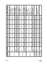
SPECIFICATIONS
Accumulator
Model
Nitrogen Charge
Volume
Solar 300LC-V
Solar 300LL
Solar 340LC-V
Solar 420LC-V
Solar 470LC-V
10 kg/cm
2
(142 psi)
320 cc (19.5 in
3
)
Summary of Contents for Solar 420LC-V
Page 1: ...Return to Master Table of Contents 1HYDRAULICS...
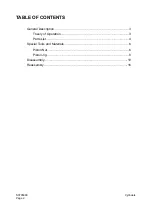
Page 33: ...S0703010K Page 2 Accumulator TABLE OF CONTENTS General Description 3 Specifications 4...
Page 43: ...S0704090K Page 8 Center Joint Swivel...
Page 63: ...S0705000 Page 20 Cylinders Return to Master Table of Contents...
Page 70: ...S0707260 Page 7 Swing Motor...
Page 74: ...S0707260 Page 11 Swing Motor SPECIAL TOOLS Figure 5...
Page 91: ...S0707260 Page 28 Swing Motor...
Page 103: ...S0707365 Page 12 Travel Motor With Gearbox A6V160HD PARTS LIST Travel Motor Figure 12 HTS6331...
Page 107: ...S0707365 Page 16 Travel Motor With Gearbox A6V160HD Travel Motor Control HTS6331 Figure 14...
Page 136: ...S0707365 Page 45 Travel Motor With Gearbox A6V160HD 29 Remove gasket Figure 91 Figure 91 3061...


