S0707260
Page 24
Swing Motor
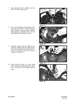
11.
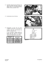
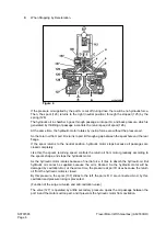
Put cylinder block (111) and retainer plate
(123) back in motor. Spherical bushing and
grooves of cylinder block splines should fit
together without undue difficulty. (Do not
try to force or pound parts together.)
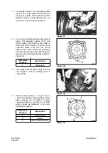
12.
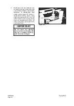
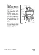
Turn motor so that front cover side (304) is
down. Put separator plates (743) and
friction plates (742) back in same order in
which they were removed. There are three
separator plates (743) and two friction
plates (742), which should be positioned
as shown in drawing below, with clearance
towards side of casing with brake valve (1,
Figure 38).
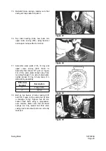
13.
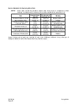
Very lightly grease larger O-rings (706 and
707, Figure 4) before replacing them in
casing (301).
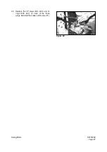
14.
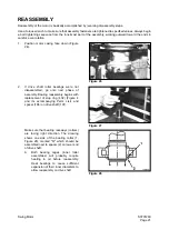
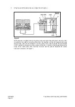
Position brake piston (1, Figure 40) in
casing. The diagram shows position of four
piston grooves (2) in relation to valve-
connected side (3), and two 8 mm bolts
which should be tightened in an even,
progressive rotation.
Reference
Number
Description
1
Brake Valve
Reference
Number
Description
1
Brake Piston
2
Groove
3
Valve-connected Side
Figure 37
Figure 38 \
Figure 39
Figure 40
Summary of Contents for Solar 420LC-V
Page 1: ...Return to Master Table of Contents 1HYDRAULICS...
Page 33: ...S0703010K Page 2 Accumulator TABLE OF CONTENTS General Description 3 Specifications 4...
Page 43: ...S0704090K Page 8 Center Joint Swivel...
Page 63: ...S0705000 Page 20 Cylinders Return to Master Table of Contents...
Page 70: ...S0707260 Page 7 Swing Motor...
Page 74: ...S0707260 Page 11 Swing Motor SPECIAL TOOLS Figure 5...
Page 91: ...S0707260 Page 28 Swing Motor...
Page 103: ...S0707365 Page 12 Travel Motor With Gearbox A6V160HD PARTS LIST Travel Motor Figure 12 HTS6331...
Page 107: ...S0707365 Page 16 Travel Motor With Gearbox A6V160HD Travel Motor Control HTS6331 Figure 14...
Page 136: ...S0707365 Page 45 Travel Motor With Gearbox A6V160HD 29 Remove gasket Figure 91 Figure 91 3061...


