background image

Copyright © 2010 CNH France S.A.

Printed in France

CNH

Lep SM700BTOC-3EN

April 2010

CRAWLER EXCAVATOR CX700B

SERVICE MANUAL

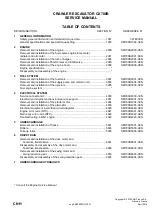
TABLE OF CONTENTS

DIVISION/SECTION

SECTION N°

REFERENCE N°

1

GENERAL INFORMATION
Safety, general information and standard torque data..................................... 1001

7-27691EN

General specifications and special torque setting ........................................... 1002

SM700B1002-3EN

2

ENGINE
Removal and installation of the engine............................................................ 2000

SM700B2000-0EN

Removal and installation of the fuel cooler, engine inter-cooler,
radiator and oil cooler ...................................................................................... 2001

SM700B2001-0EN

Removal and installation of the turbo charger ................................................. 2004

SM700B2004-0EN

Removal and installation of EGR cooler and EGR valve ................................. 2005

SM700B2005-0EN

Removal and installation of the engine hood................................................... 2006

SM700B2006-0EN

Engine specifications..............................................................................................*
Disassembly and assembly of the engine ..............................................................*

3

FUEL SYSTEM
Removal and installation of the fuel tank ......................................................... 3001

SM700B3001-0EN

Removal and installation of the supply pump and common rail ...................... 3004

SM700B3004-0EN

Removal and installation of the injectors ......................................................... 3005

SM700B3005-0EN

Fuel engine system ................................................................................................*

4

ELECTRICAL SYSTEM
Service connector kit ....................................................................................... 4000

SM350B4000-1EN

Electrical and engine functions and service support ....................................... 4001

SM700B4001-1EN

Removal and installation of the starter motor .................................................. 4004

SM700B4004-0EN

Removal and installation of the alternator ....................................................... 4005

SM700B4005-0EN

Electrical equipment & electrical circuit diagrams ........................................... 4020

SM700B4020-0EN

Engine error code (DTC) ................................................................................. 4021

SM700B4021-0EN

Main body error code (DTC)............................................................................ 4022

SM700B4022-0EN

Troubleshooting, 6WG1 engine ....................................................................... 4023

SM700B4023-0EN

5

UNDERCARRIAGE
Removal and installation of tracks ................................................................... 5001

SM700B5001-0EN

Rollers ............................................................................................................. 5003

SM700B5003-0EN

Take-up roller................................................................................................... 5005

SM700B5005-0EN

6

DRIVE TRAIN
Removal and installation of the drive motor and 

final drive transmission................................................................................ 6001

SM700B6001-0EN

Disassembly and assembly of the drive motor and 

final drive transmission................................................................................ 6002

SM700B6002-0EN

Removal and installation of the swing motor and 

swing reduction gear ................................................................................... 6003

SM700B6003-0EN

Disassembly and assembly of the swing reduction gear ................................. 6004

SM700B6004-0EN

7

UNDERCARRIAGE HYDRAULICS

*  Consult the Engine Service Manual

Summary of Contents for CX700B

Page 1: ...M700B3004 0EN Removal and installation of the injectors 3005 SM700B3005 0EN Fuel engine system 4 ELECTRICAL SYSTEM Service connector kit 4000 SM350B4000 1EN Electrical and engine functions and service...

Page 2: ...ons 8030 SM700B8030 1EN 9 UPPERSTRUCTURE Removal and installation of the counterweight 9002 SM700B9002 0EN Removal and installation of the boom dipper and bucket 9003 SM700B9003 0EN Removal and instal...

Page 3: ...CNH Copyright 2006 CNH France S A Printed in France February 2006 Lep 7 27691EN 1001 SAFETY GENERAL INFORMATION AND TORQUE SPECIFICATIONS Section 1001...

Page 4: ...L INFORMATION 3 SAFETY 4 STANDARD TORQUE DATA FOR CAP SCREWS AND NUTS 6 WARNING This symbol is used in this manual to indicate important safety messages Whenever you see this symbol carefully read the...

Page 5: ...ore information Please click here Then get the complete manual NOTE If there is no response to click on the link above please download the PDF document first and then click on it Have any questions pl...

Page 6: ...air dry DO NOT DRY BEARINGS WITH COMPRESSED AIR Needle bearings Before you press needle bearings in a bore always remove any metal protrusions in the bore or edge of the bore Before you press bearing...

Page 7: ...tor s Manual safety messages Read all safety signs on machine Clear the area of other persons Learn and practice safe use of controls before operating It is your responsibility to understand and follo...

Page 8: ...inder wear eye protection that completely encloses the eyes approved goggles or other approved eye protectors WARNING Use suitable floor service jacks or chain hoist to raise wheels or tracks off the...

Page 9: ...o the thread portion of the cap screw and then tighten Torque table Tighten cap screws and nuts according to the table below if there are no other special instructions Cap Screw Name Size Size M6 M8 M...

Page 10: ...CNH Copyright 2010 CNH France S A Printed in France April 2010 Lep SM700B1002 2EN 1002 SPECIFICATIONS AND SPECIAL TORQUE SETTINGS Section 1002...

Page 11: ...Performance 10 Main body dimensions 10 Engine 10 Cooling system 10 Capacity of coolant and lubricants 11 Air conditioning 11 Hydraulic oil filter 11 Fuel filter 11 Operating devices 12 Hydraulic syst...

Page 12: ...28 3 Boom cylinder head Boom 28 4 Arm cylinder foot Boom 29 5 Boom Arm 29 6 Arm cylinder head Arm 29 7 Bucket cylinder foot Arm 30 8 Connecting rod Arm 30 9 Compensator Bucket 30 10 Connecting rod Com...

Page 13: ...hine to your Case dealer Fill in the following lines with the required information Type serial number year of manufacture of the machine and the serial numbers of the hydraulic and mechanical componen...

Page 14: ...s yellow colored fluid is miscible with standard fluid If used to change standard fluid it is advised to drain the circuit completely before refilling with this fluid CASE AKCELA HYDRAULIC EXCAVATOR F...

Page 15: ...es proper lubrication of your engine for all operating conditions If the CASE AKCELA Multigrade No 1 ENGINE OIL cannot be obtained use the oil corresponding to one of the following categories ACEA E7...

Page 16: ...l engine is stipulated in your country check the standard for details Requirements for diesel fuel Although conditions required for the diesel fuel are illustrated above there are other requirements e...

Page 17: ...ollow these items 1 Selection of engine oil Use API grade CF 4 or JASO grade DH 1 2 Exchange the engine oil and engine oil filter element by the periodical interval reported on the Operator s Manual 3...

Page 18: ...water IMPORTANT Do not mix products of a different origin or brand The same product must be used when topping up the system Environment Before carrying out any maintenance operation on this machine an...

Page 19: ...n Overall track width 3900 mm 153 54 in during retraction 3390 mm 113 46 in Distance between tracks 3250 mm 127 95 in during retraction 2740 mm 107 87 in Width of track shoe 650 mm 25 59 in Option 750...

Page 20: ...ant for engine 52 L 13 74 gal Lubricant for travel reduction gear per side 15 L 3 96 gal Lubricant for swing reduction gear per side 13 5 L 3 57 gal Hydraulic oil 650 L 171 71 gal Capacity of hydrauli...

Page 21: ...d crystal Work mode selection status SP H A Instruments full dot liquid crystal except for hour meter Fuel gauge bar graph indicator Engine coolant temperature gauge bar graph indicator Hydraulic oil...

Page 22: ...ulic pilot method travel swing and operating machine Maximum flow 448 L min 118 35 gpm at 1850 min 1 Main relief set pressure standard 31 4 MPa 4555 psi power boost 34 3 MPa 4975 psi Overload set pres...

Reviews: