TROUBLESHOOTING
9-5
DISPLAY FAULTS
The Operator Interface will display Warnings and Alarms that pertain to the application. The following are
screens that will help diagnose a Drive or Display problem that is more serious in nature than the standard
Alarms.
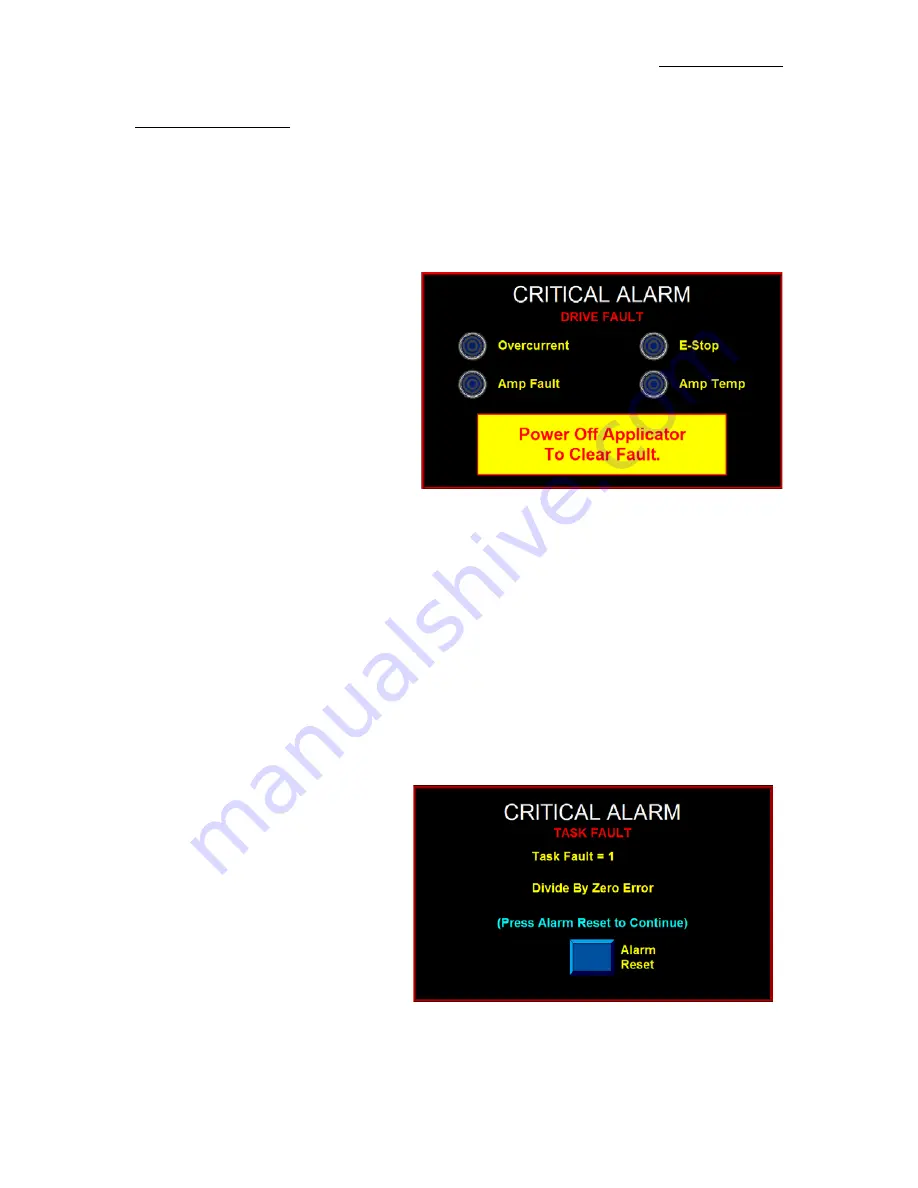
DRIVE FAULT
The Drive Fault screen will list four (4) things that will stop the Applicator from running when they occur.
Without this screen, it would be impossible to know why the Applicator stopped.
Overcurrent
-This Fault occurs when the
Drive Current has exceeded its configured
maximum value. Ensure that there are no
obstructions in the web path and that the
Unwind Brake releases properly. If these
items are correct, reduce the Motor Accel
and Decel values to their factory default
values and re-run the application. If the
mechanical system and setup is correct,
consult the factory to determine if the Drive
Current value is appropriate for your
application.
Amp Fault
- If this occurs, there has been a failure on the Drive Board. The factory should be consulted if
this occurs.
E-Stop
- In the future, the operator will be allowed to enable the E-Stop Protection Circuit to the Drive. If
this circuit were enabled and open, an E-Stop Fault would occur.
Currently this is disabled in the
Applicator.
Amp Temp
- This Alarm occurs when the Drive Amplifier Temperature exceeds the upper limit. If this
Alarm occurs, clean the Applicator’s Air filter and insure that the Cooling Fan is running properly. Also,
ensure that there are no obstructions in the web path and that the Unwind Brake releases properly. If
possible reduce Accel and Decel values to factory defaults and lower the application speed. If the
mechanical system and setup is correct, consult the factory to determine if the Drive Current value is
appropriate for your application.
TASK FAULT
If a Controller Task Fault occurs, the screen
shown to the right appears. This occurs due
to a programming issue. Contact the factory
with the Task Fault number and Fault
Explanation shown on the screen.
Summary of Contents for 360a series
Page 47: ...GENERAL SETUP PROCEDURES 5 1 360a SERIES SETUP PROCEDURES...
Page 70: ...GENENRAL MAINTENANCE 8 1 360a SERIES GENERAL MAINTENANCE PROCEDURES...
Page 102: ...13 1 360 APPLICATOR DRAWINGS 360a SERIES CE MECHANICAL AND ELECTRICAL DRAWINGS...
Page 103: ......
Page 104: ......
Page 105: ......
Page 106: ......
Page 107: ......
Page 108: ......
Page 109: ......
Page 110: ......
Page 111: ......
Page 112: ......
Page 113: ......
Page 114: ......
Page 115: ......
Page 116: ......
Page 117: ......
Page 118: ......
Page 119: ......
Page 120: ......
Page 121: ......
Page 122: ......
Page 123: ......
Page 124: ......
Page 125: ......
Page 126: ......
Page 127: ......
Page 128: ......
Page 129: ......
Page 130: ......
Page 131: ......
Page 132: ......
Page 133: ......
Page 134: ......
Page 135: ......
Page 136: ......
Page 137: ......
Page 138: ......
Page 139: ......
Page 140: ......
Page 141: ......
Page 142: ......
Page 143: ......
Page 144: ......
Page 145: ......
Page 146: ......
Page 147: ......
Page 148: ......
Page 149: ......
Page 150: ......
Page 151: ......
Page 152: ......
Page 153: ......
Page 154: ......
Page 155: ......
Page 156: ......
Page 157: ......
Page 158: ......
Page 159: ......
Page 160: ......
Page 161: ......
Page 162: ......
Page 163: ......
Page 164: ......
Page 165: ......
Page 166: ......
Page 167: ......
Page 168: ......
Page 169: ......
Page 170: ......
Page 171: ......
Page 172: ......
Page 173: ......
Page 174: ......
Page 175: ......
Page 176: ......