KA BAND OUTDOOR TWT AMPLIFIER
B-4
11. Click the checkboxes to enable the amplifier(s) connected to the host PC. The default address is
48, with each additional amplifier having a consecutive address (49,50,51...). Each amplifier can
also be given a reference name for clarification. This name will appear in the title bar of all
windows associated with that amplifier. If no name is given a default name will be assigned.
12. For more than five amplifiers, select the
Amplifiers 6-10
tab and repeat step 7. Note: Do
NOT
check the
Enabled
check box if an amplifier does not exist or is not turned on. Doing so will
significantly slow down communications between the host PC and the amplifiers.
13. Click
Apply
to establish communication with each enabled amplifier. The connection status
will read, “Connected” if successful and the amplifier model will appear in the
Type
field. If
connection is unsuccessful, an “Unable to Connect” message will appear in the
Connection
Status
field.
B.2.2 Meters
Window
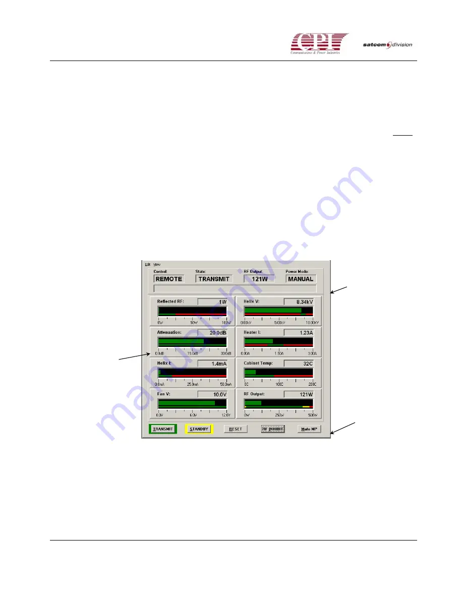
Once connected a Meters Window will appear for each amplifier. The Meters Window consists of
the Status Bar, Meters, and Control Buttons.
STATUS/EVENT
BAR
METERS
CONTROL
BUTTONS
Figure B-3 Typical Meter Screen
The control point (local/remote), system state (BONS/Standby/Transmit), RF output power
(dBm/W/dBW), and RF power mode (Manual/Auto) are displayed on the Status Bar. Events
such as faults, alarms, and inhibits are displayed in the Event Box. (See below)
INSTALLATION AND OPERATION MANUAL


