30
MYDENS
COSMOGAS
5 - INSTALLATION
5.17.2 - “Split 80/80PP” system
(polypropylene) (type C43; C53; C83;
C93)
The appliance is supplied as per standard without fittings to
connect the flue exhaust/air intake.
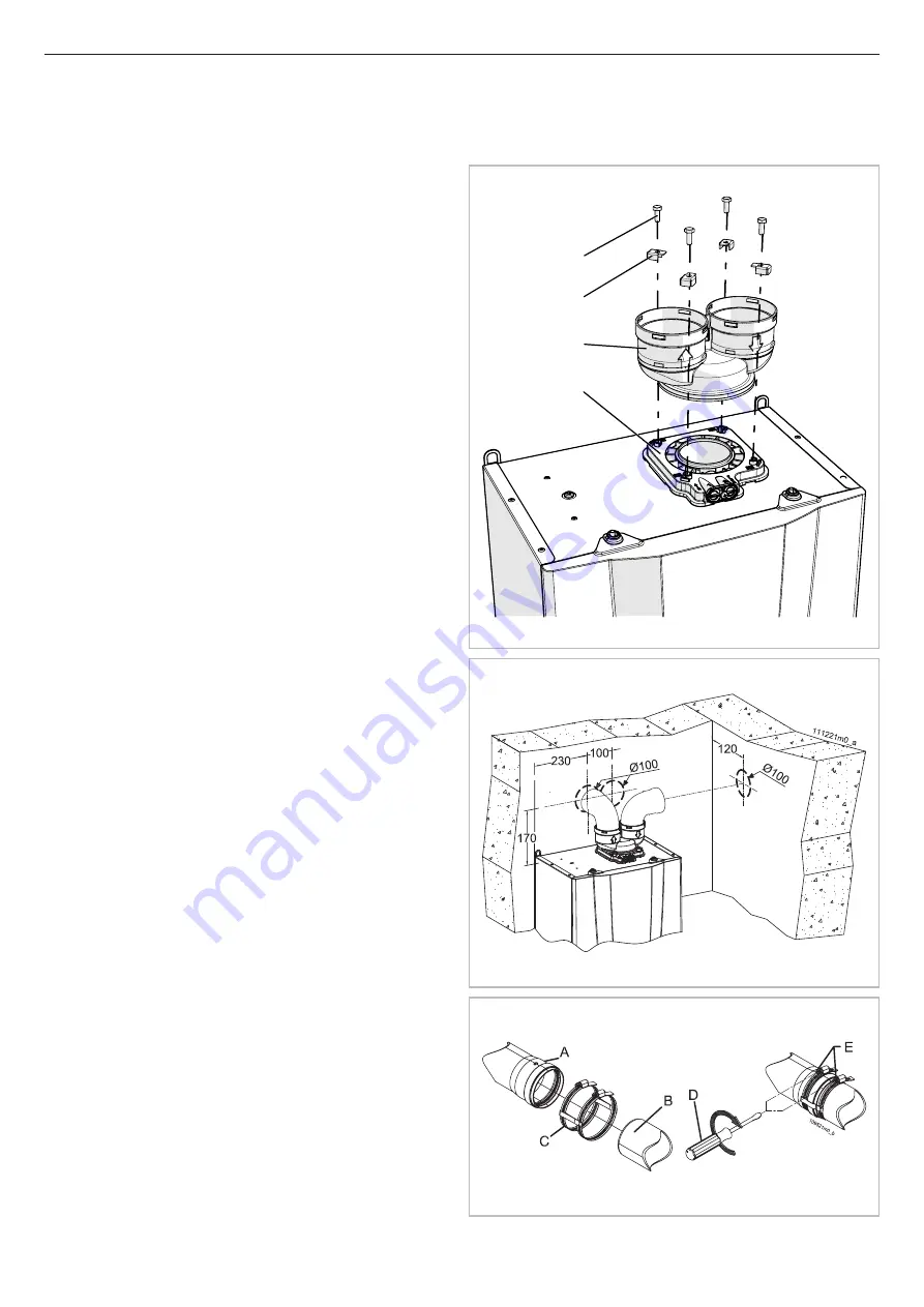
To connect the appliance to a “80/80PP Split” system, the
relevant kit must be
requested and must be installed (see Figure 26).
Fitting “A” can rotate freely 360°, guaranteeing optimum
installation versatility.
l
In the flue exhaust side, it is recommended to install
AISI 316L stainless steel or polypropylene ducts, which
are more resistant to the formation of condensate.
l
Take particular care with the installation of ducts
in the part that passes through the wall to the outside;
the normal maintenance operations must always be
possible, therefore, install the pipes in a sheath so that
they can be slid out.
l
The horizontal tracts must always have an inclination
of at least 2% towards the condensate drain device.
l
The appliance is already set up with a condensate
collector, which must be fitted to a drain pipe (see section
5.9).
a
WARNING!!! This condensate drain is designed
to drain away all of the liquid produced by a single
appliance. If more than one appliance is installed,
each appliances should be provided with its own
condensate drain.
The flue exhaust/air intake system can be extended up to
a maximum distance as indicated in section 9. Every 90°
bend has a loss equivalent to the value in section 9. Every
45° bend has a loss equivalent to the value in section 9.
a
WARNING!!! The flue exhaust terminal must be
appropriately protected against the effects of the
wind (see also section 7.17.1
Loc 22
).
a
WARNING!!! Mechanically secure the joints
between the various component elements of the
exhaust and intake ducts, through the use of fixing
systems or equivalent systems (Figure 28).
a
WARNING!!! The temperature of the exhaust
pipe can reach 90°C during operation. If the pipe
passes through walls that are sensitive to these
temperatures, insert a protective heat-insulating
sheath.
a
WARNING!!! If the air intake and flue exhaust
terminals are positioned on the same wall, they must
remain at a minimum distance of 1 metre.
a
WARNING!!! The exhaust and intake ducts
must be appropriately sustained via rigid brackets
positioned no more than 1 metre from each other.
The brackets must be fixed to rigid walls that can
support the weight of the pipe itself.
B
D
A
C
020002.01.011
Figure 26
Figure 27
Figure 28


