background image

2DF

1-3-46

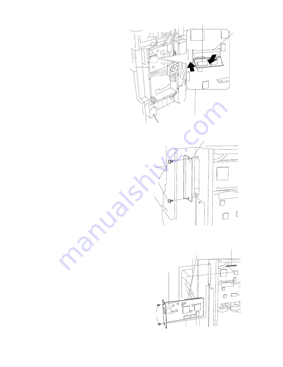
4. Insert the RTC board at an angle into the

RTC board slot on the main PCB.

5. Push the free end of the RTC board down

toward the fax board.

6. Remove 2 screws, and take off the cover.

7. Firmly push connector CN1 on the scanner

board all the way into connector CN50 on the
main PCB.

8. Fasten the scanner board with 2 screws.

Figure 1-3-98

Figure 1-3-96

Figure 1-3-97

RTC board slot

RTC board

Main PCB

Cover

Screws

Connector CN1

Connector CN50

Screws

Scanner board

Summary of Contents for Ri 2530

Page 1: ...SERVICE MANUAL Published in Apr 03 2DF70951 Ri 2530 3530 4030 Contains AD 63 DF 78 J 1402 PF 70 RA 1 PF 75 Fax System C Fax System F Revision 1...

Page 2: ...URER DISPOSE OF USED BATTERIES ACCORDING TO THE MANUFACTURER S INSTRUCTIONS ATTENTION IL Y A DANGER D EXPLOSION S IL Y A REMPLACEMENT INCORRECT DE LA BATTERIE REMPLACER UNIQUEMENT AVEC UNE BATTERIE DU...

Page 3: ...sonnel to ensure the safety of their customers their machines as well as themselves during maintenance activities Service personnel are advised to read this booklet carefully to familiarize themselves...

Page 4: ...mpliance with warning messages using this symbol WARNING Serious bodily injury or death may result from insufficient attention to or incorrect compliance with warning messages using this symbol CAUTIO...

Page 5: ...or dusty place This may cause fire or electric shock Do not install the copier near a radiator heater other heat source or near flammable material This may cause fire Allow sufficient space around th...

Page 6: ...clean Dirt on them can cause abnormally high temperatures Do not remove the ozone filter if any from the copier except for routine replacement 2 Precautions for Maintenance WARNING Always remove the...

Page 7: ...t all the caution labels that should be present on the machine according to the instruction handbook are clean and not peeling Replace with new ones if necessary Handle greases and solvents with care...

Page 8: ...ion 1 3 17 1 3 6 Installing the paper feed desk option 1 3 18 1 3 7 Installing the large paper deck option 1 3 21 1 3 8 Installing the saddle finisher switchback unit option 1 3 25 1 3 9 Installing th...

Page 9: ...ot operate 1 5 52 8 Cooling fan motor 1 does not operate 1 5 52 9 Cooling fan motor 2 does not operate 1 5 52 10 Cooling fan motor 3 does not operate 1 5 52 11 Cooling fan motor 4 does not operate 1 5...

Page 10: ...ing paper feed and separation pulleys 1 6 3 2 Detaching and refitting the bypass separation bypass papaer feed and bypass forwarding pulleys 1 6 5 3 Adjustment after roller and clutch replacement 1 6...

Page 11: ...section 2 1 7 1 Original scanning 2 1 8 2 Image printing 2 1 9 2 1 4 Developing section 2 1 12 1 Formation of magnetic brush 2 1 13 2 Computing the absolute humidity 2 1 14 3 Single component developi...

Page 12: ...1 1 5 2DF Maintenance parts list 2 4 15 Periodic maintenance procedures 2 4 16 Optional devices supplied parts list 2 4 18 General wiring diagram 2 4 20...

Page 13: ...copies min B4 81 2 14 23 copies min A4 11 81 2 35 copies min A4R 81 2 11 25 copies min 40 cpm copier A3 11 17 19 copies min B4 81 2 14 23 copies min A4 11 81 2 40 copies min A4R 81 2 11 25 copies min...

Page 14: ...252 5 D 291 3 H Weight Approx 79 kg 165 lbs Floor requirements 1356 W 646 D mm 533 8 W 252 5 D Functions Self diagnostics preheat automatic copy density control original size detection auto paper size...

Page 15: ...handle 4 Conveying cover 5 Bypass tray 6 Insert guides 7 Toner container 8 Toner container release lever 9 Toner disposal tank 0 Cleaning shaft Front cover Main switch Copy store section Platen Origi...

Page 16: ...selection key Indicator Facsimile priority output key Indicator Printer priority output key Indicator Brightness adjustment control dial Copier key Indicator Printer key Indicator Scanner key Indicat...

Page 17: ...r path Figure 1 1 4 Machine cross section 1 Paper feed section 2 Main charging section 3 Optical section 4 Developing section 5 Transfer and separation section 6 Cleaning and charge erasing section se...

Page 18: ...1 1 4 As viewed from machine rear 1 Drive motor gear 2 Drum gear Z76H Z30H 3 Drum gear Z70H 4 Gear Z76H Z35H 5 Gear Z50H 6 Gear Z36S Z31H 7 Gear Z37H 28H 8 Gear Z34H 9 Registration clutch gear 0 Gear...

Page 19: ...Z35S 3 Feed gear Z25 4 Feed gear Z25 5 Feed gear Z25 6 Feed gear Z25 7 Gear Z41S Z24S P30 8 Upper paper feed clutch gear 9 Paper feed drive belt 0 Gear Z41S Z24S Lower paper feed clutch gear Gear Z41...

Page 20: ...void direct sunlight or bright lighting Ensure that the photoconductor will not be exposed to direct sunlight or other strong light when removing paper jams Avoid extremes of temperature and humidity...

Page 21: ...ht source units 1 and 2 Install the toner container Connect the power cord Load paper Make test copies Print out the user setting list Output an own status report maintenance item U000 Exit maintenanc...

Page 22: ...andles for transport on the right and left sides and hold them For the left front handle for transport open the door and push it into the machine before pulling out the handle Handle for transport Han...

Page 23: ...er 2 Power cord 3 Upper left pad 4 Upper right pad 5 Outer case 6 Inner frame 7 Lower right pad 8 Lower left pad 9 Skid 0 Bottom pad Machine cover Bar code labels Belt Eject spacer Spacer Plastic bag...

Page 24: ...e pad at the eject section 3 Remove the three tapes holding the pins for light source units 1 and 2 4 Remove the tape holding the conveying cover 5 Remove the two tapes holding the power cord 120 V sp...

Page 25: ...2 Figure 1 3 5 Figure 1 3 6 Remove the pins holding light source units 1 and 2 Tape Light source unit 2 pin Light source unit 1 pins Install the optional paper feed desk or large paper deck Install t...

Page 26: ...approximately 10 times in the horizontal direction to stir toner 4 Gently push the toner container into the copier along the rails Push the container all the way into the copier until it locks in plac...

Page 27: ...Enter 130 using the numeric keys and press the start key 3 Press the start key to execute the maintenance item The drive stops within approximately 5 minutes 4 Press the stop clear key 1 Load paper in...

Page 28: ...among No 1 to 4 based on installation of the fax board and the printer board If the DF has not been installed select a function sheet among No 5 to 8 based on installation of the fax board and the pr...

Page 29: ...and single counts Turning auto start function on off Setting auto clear time Turning auto preheat energy saver function on off Switching copy operation at toner empty detection Changing the copy count...

Page 30: ...er the management code Make copy default settings page 1 3 11 Enter the management code Make machine default settings page 1 3 13 Output the setting list page 1 3 14 Set the language page 1 3 14 Start...

Page 31: ...ment list 1 Press the Print the list key If A4 11 81 2 paper is present the list is automatically printed out Otherwise select the paper source and press the start key 3 Copy default Exposure mode Sel...

Page 32: ...adjust default margin width Setting range 0 to 3 4 inch specifications 0 to 18 mm metric specifications Border erase width Sets the default setting of the border erase width for the border erase mode...

Page 33: ...izing Sets whether or not to display the paper size key of the basic screen when copying with the bypass tray 1 Select Check bypass express and press the Change key 2 Selct On or Off Auto shutoff time...

Page 34: ...ng reports 1 Press the Print form key 2 Select the report Copy report Option report Counter report Machine report 6 Language Switches the language to be displayed on the press panel 1 Press the Langua...

Page 35: ...head screws P N B2303060 One 1 M3 bronze nut P N C2303000 Procedure 1 Fit the key counter socket assembly to the key counter retainer using the two screws and nut 2 Fit the key counter mount to the ke...

Page 36: ...ner on the copier using the screw 9 Insert the key counter into the key counter socket assembly 10 Turn the main switch on and enter the maintenance mode 11 Run maintenance item U204 and select KEY CO...

Page 37: ...the drawer heater out of the machine through the aperture of the rear frame 4 Remove the four screws and the two connectors and then remove the power source unit from the rear side of the machine 5 Re...

Page 38: ...3 20 2 Place the copier on top of the paper feed desk with the positioning pins at the front left and right of the paper feed desk aligned with the holes in the base of the copier 3 Secure the copier...

Page 39: ...desk into the connector on the copier 8 Route the harness through the clamp on the retainer 9 Fit the retainer using the screw removed in step 6 and the two CVM4 06 cross head chromate binding screws...

Page 40: ...e other the rear using the two M4 10 chrome TP screws such that they make contact with the floor Note Do not fit the stays if the finisher is to be installed 13 Connect the copier power plug to the wa...

Page 41: ...er deck with the positioning pins at the front left and right of the large paper deck aligned with the holes in the base of the copier 3 Secure the copier to the large paper deck using the two pins 4...

Page 42: ...gure 1 3 31 5 Remove the screw and then the cover from the rear of the large paper deck 6 Remove the screw from the rear of the copier 7 Insert the 12 pin connector of the large paper deck into the co...

Page 43: ...them to level the machine 11 Fit the stay to the lower left of the large paper deck toward the rear using the two M4 16 chrome TP screws such that it makes contact with the floor Note Do not fit the s...

Page 44: ...ecure the lateral size adjusters using the screw for each 5 Move the front and rear sliders two at each point outward until they make contact with the lateral size adjusters Steps 6 to 9 are for metri...

Page 45: ...cover such that the projections on the cover fit into the two ends of the curl eliminator 4 Secure the curl eliminator using the two screws removed in step 2 5 Close the conveying cover 6 Fit the latc...

Page 46: ...om CN4 on the main PCB and connect it to J2 on the IPC PCB 9 Connect J1 on the IPC PCB to CN15 on the main PCB 10 Insert the three board supports of the IPC PCB into the main PCB to secure them 11 Ref...

Page 47: ...en the switchback unit is to be installed 14 Attach a spacer to each end of the rail retainer using two M4 6 binding screws for each 15 Orient the guide rail such that its pulley is positioned toward...

Page 48: ...ote When installing the switchback unit use screw hole a in the guide rail when not installing the switchback unit use screw hole b in the guide rail 19 Adjust the position of the rail fixing plate so...

Page 49: ...and insert the stapler unit into the finisher 22 Close the front panel Installing the switchback unit 1 Remove the two support rubbers on the right of the finisher and loosely fit the two M3 8 binding...

Page 50: ...k of the switchback unit on the loosely fitted M3 8 binding screws 5 Tighten the loosely fitted M3 8 binding screws 6 Secure the switchback unit using two M4 12 TP screws 7 Close the switchback unit 8...

Page 51: ...rted see step 8 11 Fit the two support rubbers removed in step 1 to the switchback unit 12 If the finisher and the copier do not engage securely perform the following finisher height adjustment Adjust...

Page 52: ...r is joined to the copier viewed from the machine front Note Turning the adjustment bolts clockwise lowers the finisher while turning them counterclockwise lifts the finisher 5 Adjust the height of th...

Page 53: ...of the four casters 8 Refit the two covers and four caps Connecting the signal cable 1 Connect the signal cable of the finisher to the copier If the switchback unit has been installed connect the sig...

Page 54: ...main switch on 4 Run maintenance item U211 to set SADF 25 cpm copier only 5 Place the original on the DF and make a test copy Check the operation and the copy image 6 If the copy image is different f...

Page 55: ...sheet to the auxiliary power source retainer 6 Fasten the auxiliary power source PCB together with the upper sheet to the auxiliary power source retainer using three M3 06 chrome binding screws 7 Pass...

Page 56: ...the 2 screws holding the printer system in place and pull the printing system out of the shield cover 10 Remove 13 screws and take off the shield cover 11 Move the film out of the way to the left and...

Page 57: ...nnector CN7 NCU board connector CN3 Battery connector CN6 14 Remove the film that fixes the three positive connectors of the power source PCB from the optional interface mounting plate Important Dispo...

Page 58: ...e M3 06 chrome binding screw 15 Connect the three positive connectors on the power board to the corresponding connectors on the auxiliary power source PCB as follows White positive connector TB1 white...

Page 59: ...2DF 1 3 39 This page is intentionally left blank...

Page 60: ...main PCB Pull the CN44 housing out to release the connector lock then insert the cable and then push the housing back in Important Be sure to push the fax cable all the way in and be sure that the co...

Page 61: ...er into place with 13 screws 25 Remove 1 screw and take off the modular cover Shield cover Screws Screw Modular cover Figure 1 3 78 Screw Holes Modular cover 26 Hang the modular cover onto the holes o...

Page 62: ...tem into the shield cover fastening it into place with 2 screws Screws Printing system Rear cover Screws 28 Reattach the rear cover with 13 screws 29 Adhere the certification labels to the rear cover...

Page 63: ...eric keys on the operation panel In Asia use the PQRS TUV WXYZ label and do not use the PRS TUV WXZ and OPER labels Figure 1 3 82 Figure 1 3 83 Power label Main switch 1 4 7 5 6 9 8 0 2 3 ABC DEF MNO...

Page 64: ...tration At the position of the version number of the software is displayed 8 After completing the installation run a communications test to confirm that the fax system is working correctly Japan Austr...

Page 65: ...e printing system all the way in along the rails and fasten it with 2 screws Install the optional network printer board 3 Remove 2 screws and take off the cover 4 Push the network printer board all th...

Page 66: ...position shown in the illustration and pass the wire though the clamp If a wing tray is installed attach the other clamp to the wing tray and pass the wire through both clamps Installing the Optional...

Page 67: ...r cover Figure 1 3 95 If the printing system is installed 2 Remove the 2 screws holding the printer system in place and pull the printing system out of the shield cover Rear cover Screws Screws Printe...

Page 68: ...d the fax board 6 Remove 2 screws and take off the cover 7 Firmly push connector CN1 on the scanner board all the way into connector CN50 on the main PCB 8 Fasten the scanner board with 2 screws Figur...

Page 69: ...ield cover into place with 13 screws If the printing system was installed 10 Reinstall the printing system into the shield cover fastening it into place with 2 screws Shield cover Screws Screws Printi...

Page 70: ...Screws Struts 3 Insert the nut plates into the paper conveying bases 4 Raise the release lever of the conveying unit open the conveying unit a little and hang the hook sections in the front and rear o...

Page 71: ...nit Connector Groove Hamess 8 pin connector Conveying cover Conveying cover Screws Struts Figure 1 3 105 Figure 1 3 106 8 Insert the removed conveying cover in the horizontal direction and reattach th...

Page 72: ...deformed resulting in a malfunction Figure 1 3 107 Upper left cover Screw Pin 2 Open the conveying cover and the front cover 3 Loosen the two screws on the left side and the screw on the front side op...

Page 73: ...ver with the mounting plate 6 Remove the two screws and then remove the inner ejection cover Figure 1 3 110 Screws Inner ejection cover 7 Remove the screw located at the front of the static charge eli...

Page 74: ...t has been fitted to the transfer unit 11 Insert the metal hook of the transfer unit into the oblong hole of the frame of the copier and secure it using a TP A bronze screw M3 05 Insert the projection...

Page 75: ...connect the connector white of the intermediate tray to the transfer unit Connect the connectors gray to the connectors of the copier as shown in the illustration Connect the gray connector with more...

Page 76: ...side to secure the cover with the copier secure the front side using the screw that has been removed in step 3 and secure the right side using a TP A chrome screw M3 05 18 Close the conveying cover an...

Page 77: ...into the stapler 21 Close the staple cover 22 Insert the power plug of the copier into an outlet and turn the main switch on 23 Select the staple mode and make a stapled copy to check that stapling i...

Page 78: ...121 Figure 1 3 122 5 Remove the two screws and remove the ejection cover with the mounting plate Screws Screw Hook Left front cover Ejection cover Screws 2 Open the conveying cover and the front cover...

Page 79: ...Insert the job separator into the copier from the front side and slide it to the left Secure the front side using a TP A bronze screw M3 05 and the rear side using a pin Check to see if the branch pr...

Page 80: ...the left transfer cover and the front cover Fit the left front cover JS to the location to which the upper front cover that has been removed in step 3 was fitted Figure 1 3 125 Connector Connector of...

Page 81: ...rear cover 3 Remove 13 screws and take off the shield cover If the printing system is installed 2 Remove the 2 screws holding the printer system in place and pull the printing system out of the shield...

Page 82: ...assembly 6 Fasten the NCU board assembly into place from the bottom with two M3 06 chrome binding screws 7 Connect the three connectors from the NCU board assembly to the corresponding connectors on t...

Page 83: ...liary power source PCB assembly CN1 FAX PCB Power cable CN1 Auxiliary power source PCB assembly Figure 1 3 134 10 Connect the three positive connectors on the power board to the corresponding connecto...

Page 84: ...8 Opening 2 pin connector with green cable 2 pin connector Fax board Figure 1 3 137 14 Unlock YC1 on the fax board by pulling its connector housing 15 Hold the fax cable with its conductive side facin...

Page 85: ...e 1 3 139 19 Hang the modular cover onto the holes on the controller box cover and fasten it into place with 1 screw Screw Modular cover Screw Holes Modular cover Figure 1 3 140 17 Fasten the shield c...

Page 86: ...fastening it into place with 2 screws Screws Printing system Figure 1 3 142 21 Reattach the rear cover with 13 screws Rear cover Screws Figure 1 3 143 22 Adhere the certification labels to the rear co...

Page 87: ...TUV WXZ and OPER labels 25 Connect the L terminal to the phone circuit using a modular connector cable Important On 120 V systems use the included modular connector cable to make the connection 26 Aft...

Page 88: ...r 001 using the cursor up down keys or numeric keys and press the start key Enter the maintenance item number using the cursor up down keys or numeric keys The selected maintenance item is run Press t...

Page 89: ...61 Turning the exposure lamp on U063 Adjusting the shading position 0 U065 Adjusting the scanner magnification Main scanning direction auxiliary scanning direction 0 2 U066 Adjusting the leading edge...

Page 90: ...xing counts U196 Turning the fixing heater on U199 Checking the fixing temperature U200 Turning all LEDs on U201 Initializing the touch panel U202 Setting the KMAS host monitoring system U203 Operatin...

Page 91: ...de operation MODE0 U402 Adjusting margins of image printing U403 Adjusting margins for scanning an original on the contact glass U404 Adjusting margins for scanning an original from the DF U407 Adjust...

Page 92: ...NTENANCE List of the current settings of the maintenance modes JAM List of the paper jam occurrences SERVICE CALL List of the service call occurrences 3 Press the start key The interrupt copy mode is...

Page 93: ...number is set and the screen for selecting a maintenance item No is displayed Completion To exit this maintenance item without changing the current setting press the stop clear key The screen for sel...

Page 94: ...d pulley remove all the paper in the drawers or the drawers With the paper present the paper feed pulley does not operate 6 Press the start key The operation starts Copy operation is simulated without...

Page 95: ...machines i e settings for counters service call history and mode settings As a result initializes the backup RAM according to the specifications depending on the destination selected in U252 Purpose...

Page 96: ...played U031 Checking switches for paper conveying Description Displays the on off status of each paper detection switch on the paper path Purpose To check if the switches for paper conveying operate c...

Page 97: ...Optinal Completion Press the stop clear key The screen for selecting a maintenance item No is displayed U033 Checking solenoid operation Description Turns each solenoid on Purpose To check the operat...

Page 98: ...op clear key The screen for selecting a maintenance item No is displayed U038 Checking the copier cover switch Description Displays the on off status of each cover switch Purpose To check if the switc...

Page 99: ...ning direction POLYGON MOTOR Increasing the setting makes the image longer in the main scanning direction and shorter in the auxiliary scanning direction decreasing the setting makes the image shorter...

Page 100: ...being performed copying from an original can be made in interrupt copy mode Completion Press the stop clear key at the screen for selecting an item The screen for selecting a maintenance item No is d...

Page 101: ...opy mode Completion Press the stop clear key at the screen for adjustment The screen for selecting a maintenance item No is displayed U065 Adjusting the scanner magnification Adjustment See pages 1 6...

Page 102: ...start key The screen for executing is displayed Setting 1 Change the setting using the cursor up down keys Description Setting range Initial setting Change in value per step Original conveying motor s...

Page 103: ...tial setting Change in value per step LEAD EDGE ADJ DF leading edge registration 20 to 20 8 0 17 mm TRAIL EDGE ADJ DF trailing edge registration 10 to 10 0 0 17 mm Increasing the setting moves the cop...

Page 104: ...ing range Initial setting Change in value per step DF center line 39 to 39 15 0 17 mm Increasing the setting moves the image to the right and decreasing it moves the image to the left 2 Press the star...

Page 105: ...selected conditions 7 To stop operation press the stop clear key Completion Press the stop clear key when scanning stops The screen for selecting a maintenance item No is displayed U074 Adjusting the...

Page 106: ...ress the start key Display Description ON OFF Setting the mode on off DATA Setting the reference data for identifying dust Setting the mode on off 1 Select ON or OFF The selected item is displayed in...

Page 107: ...mode is turned on the resolution may be slightly reduced 2 Press the start key The value is set The screen for selecting a maintenance item No is displayed Completion To exit this maintenance item wit...

Page 108: ...d rear When scanning is performed after shading there should be no difference between respective values Any differences between the values at machine front and rear indicates that scanner problem caus...

Page 109: ...ayed 3 Press the start key Auto adjustment starts When adjustment is complete each adjusted value is displayed Display Description SCAN CENTER Scanner center line SCAN TIMING Scanner leading edge regi...

Page 110: ...Description DARKER Change in density when manual density is set dark LIGHTER Change in density when manual density is set light 2 Adjust the setting using the cursor up down keys Display Setting rang...

Page 111: ...for selecting an item press the stop clear key Setting 1 Select an item to be set Display Description Setting range Initial setting LEVEL Detection sensor threshold value 0 to 255 170 WAIT TIME Origi...

Page 112: ...hod Press the start key The screen for selecting an item is displayed Setting 1 Select the item to be set The selected item is displayed in reverse 2 Change the setting using the cursor up down keys D...

Page 113: ...item No is displayed Setting 1 Enter a six digit count using the numeric keys 2 Press the start key The count is set and the screen for selecting a maintenance item No is displayed Completion To exit...

Page 114: ...nd whether or not toner remains in the developing unit 0 No 1 Yes are displayed Supplement The following data is also renewed or cleared by performing this maintenance item Clearing the developing dri...

Page 115: ...stop clear key The screen for selecting a maintenance item No is displayed U157 Checking clearing the developing drive time Description Displays the developing drive time for checking clearing or cha...

Page 116: ...rature Purpose Normally no change is necessary However can be used to prevent curling or creasing of paper or solve a fixing problem on thick paper Method 1 Press the start key The screen for selectin...

Page 117: ...ing a maintenance item No is displayed U162 Stabilizing fixing forcibly Description Stops the stabilization fixing drive forcibly regardless of fixing temperature Purpose To forcibly stabilize the mac...

Page 118: ...o check fixing heaters turning on Method 1 Press the start key The screen for selecting an item is displayed 2 Select the heater to be turned on The selected heater turns on for 3 s and then turns off...

Page 119: ...he touch panel after it is replaced Method 1 Press the start key The screen for executing is displayed and the key displayed at the upper left of the touch panel flashes 2 Press on the center of the k...

Page 120: ...starts for the selected magnification 6 To stop continuous operation press the stop clear key Completion Press the stop clear key when the operation stops The screen for selecting a maintenance item N...

Page 121: ...onds 5 When the LEDs go off press the start key All the LEDs light for 10 seconds again Completion Press the stop clear key The screen for selecting a maintenance item No is displayed U208 Setting the...

Page 122: ...the built in finisher Description If the machine is equipped with an optional built in finisher this mode sets whether A5 51 2 81 2 size paper is output to the machine internal tray or not Purpose If...

Page 123: ...aple copying Setting the number of sheets of stack on the main tray 1 Change the setting using the cursor up down keys Setting Description 0 3000 sheet finisher 3000 sheets built in finisher 500 sheet...

Page 124: ...1 4 37 2DF This page is intentionally left blank...

Page 125: ...n each motor off press the stop clear key Completion Press the stop clear key when operation stops The screen for selecting a maintenance item No is displayed U244 Checking the DF switches Description...

Page 126: ...ed 51 2 81 2 81 2 14 81 2 11 11 17 11 15 11 81 2 000 49 664 50 176 61 440 61 952 103 936 104 448 139 264 139 776 146 432 146 994 197 120 197 632 197 720 223 232 256 For example if any value between 10...

Page 127: ...ion is not proper To adjust when registration is not proper or staple position is shifted in the staple sort mode Start 1 Press the start key The screen for selecting an item is displayed 2 Select the...

Page 128: ...Select the desired cursor position The selected item is displayed in reverse 2 Change the setting using the cursor up down keys Display Description Setting range Initial setting FRONT Front side regi...

Page 129: ...is displayed in reverse and operation starts Large paper deck Display Motors and clutches Operation LCF MOT Conveying motor CM On for 5 s B CL Conveying clutch CCL On for 1 s PCL1 Paper feed clutch 1...

Page 130: ...1 4 41 2DF This page is intentionally left blank...

Page 131: ...d to the mail trays in ascending order from mail tray 1 to mail tray 7 repeatedly Interrupt copy mode While this maintenance item is being performed copying from an original can be made in interrupt c...

Page 132: ...maintenance item U020 in order to return the setting to the value before replacement or initialization Method Press the start key The screen for selecting an item is displayed Setting 1 Select the de...

Page 133: ...No is displayed Completion To exit this maintenance item without changing the current setting press the stop clear key The screen for selecting a maintenance item No is displayed U254 Turning auto st...

Page 134: ...electing a maintenance item No is displayed U256 Turning auto preheat energy saver function on off Description Selects if the auto preheat energy saver function is turned on When set to ON the time to...

Page 135: ...selecting a maintenance item No is displayed U260 Changing the copy count timing Description Changes the copy count timing for the total counter and other counters Purpose To be set according to user...

Page 136: ...selecting a maintenance item is displayed Completion To exit this maintenance item without changing the current setting press the stop clear key The screen for selecting a maintenance item is displaye...

Page 137: ...ired according to the number of copies the user makes Method Press the start key The current setting is displayed Setting 1 Set the number of sheets o to 250 using the numeric keys or cursor up down k...

Page 138: ...1 4 47 2DF This page is intentionally left blank...

Page 139: ...o 3 0 0 3 0 3 0 3 OTHER Size conversion factor for non standard sizes 0 0 to 3 0 1 0 1 0 1 0 Inch models Display Description Setting Initial setting COPY PRI FAX 11 17 Size conversion factor for 11 17...

Page 140: ...the job separator or duplex unit is installed 150 When the finisher is installed 100 3 Press the start key The setting is set Completion Press the stop clear key The screen for selectiong a maintenanc...

Page 141: ...intenance cycle ends When the difference between the number of copies of the maintenance cycle and that of the maintenance count reaches the set value the message is displayed This maintenance mode is...

Page 142: ...tep A MARGIN Left margin 0 to 10 2 0 5 mm B MARGIN Leading edge margin 0 to 10 3 0 5 mm C MARGIN Right margin 0 to 10 2 0 5 mm D MARGIN Trailing edge margin 0 to 10 2 0 5 mm Increasing the setting mak...

Page 143: ...item No is displayed Completion To exit this maintenance item without changing the current setting press the stop clear key The screen for selecting a maintenance item No is displayed U501 Setting im...

Page 144: ...setting press the stop clear key The screen for selecting a maintenance item No is displayed U540 Adjusting the auxiliary scanning magnification Description Changes the magnification ratio in the aux...

Page 145: ...em No is displayed U902 Checking clearing finisher punch count Description Sets the punch limit and displays and clears the punch hole scrap count when the optional finisher is attached Purpose Sets t...

Page 146: ...creen for selecting a maintenance item No is displayed U904 Checking clearing the service call counts Description Displays or clears the service call code counts by types Purpose To check the service...

Page 147: ...STAPLE Frequency the stapler has been activated PUNCH Frequency the punch has been activated STACK Frequency the stacker has been activated Clearing 1 Select the item to be cleared The selected item i...

Page 148: ...ta Description Clears the accumulated black ratio data for A4 sheets Purpose To clear data as required at times such as during maintenance service Method 1 Press the start key 2 Press CANCEL on the to...

Page 149: ...e To check the machine operation situation Also to clear the data Method Press the start key Outputting the list 1 Select OUTPUT 2 Press the start key to output the list Clearing 1 Select COUNT CLEAR...

Page 150: ...without changing the accumulated time press the stop clear key The screen for selecting a maintenance item No is displayed U991 Checking clearing the scanner count Description Displays or clears the...

Page 151: ...1 4 56 2DF This page is intentionally left blank...

Page 152: ...Display Description PRINTER COUNT Print count of the printer FAX COUNT Print count of the fax Clearing 1 Select the count to be cleared 2 Press the reset key 3 Press the start key The count is cleare...

Page 153: ...G pattern Method 1 Press the start key The screen for selecting an item is displayed 2 Select the VTC PG pattern to be output Display PG pattern to be output Purpose Center line adjustment Lateral squ...

Page 154: ...vers to turn safety switch 1or 2 off and on Misfeed in drawer Jam code 10 Jam code 12 Jam code 13 Jam code 15 Jam code 16 Jam code 17 Misfeed inside conveying cover Jam code 18 Jam code 21 Jam code 22...

Page 155: ...r conveying section Misfeed in bypass vertical paper conveying section Multiple sheets in copier paper feed section Multiple sheets in copier vertical conveying section Multiple sheets in bypass verti...

Page 156: ...2 FSW3 DUPPCSW RSW RCL BYPFCL BYPPFCL BYPFSW PFCL U PFCL L DPFCL U DPFCL L ESW FSSW PCSW FCL1 DUPFCL FCL2 FCL3 DFSW DFCL OFSW SRDF Built in finisher Paper feed desk Large paper deck Duplex unit OSBSW...

Page 157: ...1 5 2 No paper feed from large paper deck jam code 12 Feed switch 3 FSW3 does not turn on within 650 ms of paper feed clutch 1 PFCL1 turning on PFCL1 OFF ON OFF ON FSW3 650 ms Timing chart 1 5 3 No p...

Page 158: ...g on PFCL2 OFF ON OFF ON PPSENS3 290 ms Timing chart 1 5 7 Jam in large paper deck horizontal paper conveying section jam code 16 Paper path sensor 2 PPSENS2 does not turn on within 310 ms of the pape...

Page 159: ...Timing chart 1 5 13 Misfeed in bypass vertical paper conveying section jam code 20 The registration switch RSW does not turn on within 3932 ms of the bypass feed switch BYPFSW turning on 3932 ms BYPF...

Page 160: ...hin the time required to convey the length of the used paper size plus 1123 ms of turning on OFF ON Paper size 1123 ms BYPFSW Timing chart 1 5 19 Feed switch 1 FSW1 does not turn off within 841 ms of...

Page 161: ...OFF ON Timing chart 1 5 24 Feed switch 1 FSW1 does not turn off within 1910 ms of feed switch 2 FSW2 turning on 1910 ms FSW2 FSW1 OFF ON OFF ON Timing chart 1 5 25 Feed switch 2 FSW2 does not turn off...

Page 162: ...RSW does not turn off within 1657 ms of feed switch 1 FSW1 turning on 1657 ms FSW1 RSW OFF ON OFF ON Timing chart 1 5 30 Secondary paper feed does not start jam code 35 Secondary paper feed does not...

Page 163: ...34 Misfeed in job separator eject section jam code 51 The job separator eject switch JBESW does not turn on within 2050 ms of the feedshift switch FSSW turning on 2050 ms FSSW JBESW OFF ON OFF ON Tim...

Page 164: ...ms FSSW Timing chart 1 5 39 The feedshift switch FSSW does not turn off within 2898 ms of the registration switch RSW turning off 2898 ms RSW FSSW OFF ON OFF ON Timing chart 1 5 40 The feedshift switc...

Page 165: ...n switchback operation Timing chart 1 5 44 7 Duplex section Duplex paper conveying section 1 jam code 60 The duplex paper conveying switch DUPPCSW does not turn on within 1285 ms of the feedshift swit...

Page 166: ...ch OFSW does not turn on within 800 ms of the start of forward rotation of the original feed motor OFM OFM OFF ON Fwd OFF ON OFSW 800 ms Timing chart 1 5 49 An original jam in the original feed convey...

Page 167: ...le sided original mode the DF timing switch DFTSW turns off within 474 ms of turning on DFTSW OFF ON 474 ms Timing chart 1 5 54 An original jam remaining after retries jam code 74 In the single sided...

Page 168: ...ing switch does not turn on within 1550 ms of the signal requesting paper ejection is output from the copier Intake jam jam code 82 During paper intake from the copier the paper conveying switch PCSW...

Page 169: ...eplace feed switch 2 if indication of the correspond ing switch on the operation panel is not displayed in reverse Run maintenance item U031 and turn feed switch 3 on and off manually Replace feed swi...

Page 170: ...c tuator Defective feed switch 3 Change the paper Check visually and replace any deformed pulleys Check visually and replace feed switch 2 if its actuator is broken Run maintenance item U031 and turn...

Page 171: ...ass feed switch Check if the bypass paper feed clutch malfunctions Electrical problem with the bypass paper feed clutch Run maintenance item U247 and select the desk upper paper feed clutch on the ope...

Page 172: ...Broken feed switch 2 ac tuator Change the paper Check visually and replace With 5 V DC present at CN6 12 on the deck main PCB check if CN6 11 on the deck main PCB remains low when paper path sensor 3...

Page 173: ...e registration switch on and off manually Replace the switch if indication of the corre sponding switch on the operation panel is not displayed in re verse Check and repair if necessary Check visually...

Page 174: ...k main PCB remains low when the desk feed switch is turned on and off If it does replace the desk feed switch Check visually and replace the bypass feed switch if its actuator is broken Run maintenanc...

Page 175: ...manually Replace the bypass feed switch if indication of the corresponding switch on the operation panel is not displayed in reverse Run maintenance item U031 and turn the registration switch on and o...

Page 176: ...ct switch on and off manually Replace the eject switch if indication of the corre sponding switch on the operation panel is not displayed in re verse Check visually and replace the feedshift switch if...

Page 177: ...5 4 on the switchback unit main PCB remains low when the switchback eject switch is turned on and off If it does replace the switchback eject switch Check visually and replace the feedshift switch if...

Page 178: ...sary Run maintenance item U244 and turn the DF timing switch on and off manually Replace the switch if indication of the corre sponding switch on the operation panel is not displayed in re verse Run m...

Page 179: ...formed With 5 V DC present at CN4 9 on the finisher main PCB check if CN4 10 on the finisher main PCB remains high or low when the paper conveying switch is turned on and off If it does re place the p...

Page 180: ...splayed as a code consisting of C followed by a number between 0030 and 8500 indicating the nature of the problem A message is also displayed requesting the user to call for service After removing the...

Page 181: ...x board Poor contact in the connector ter minals Defective main PCB Defective deck main PCB desk main PCB Replace the fax board and check for cor rect operation Turn safety switch 1 off and back on an...

Page 182: ...he specified period of time Poor contact in the connector ter minals Defective main PCB Defective finisher main PCB Poor contact in the connector ter minals Defective main PCB Defective mailbox main P...

Page 183: ...ken gears or couplings of the lower lift motor Defective lower lift motor Poor contact of the lower lift motor connector termi nals Defective lower lift limit switch Poor contact of the lower lift lim...

Page 184: ...r terminals Broken gears of couplings of the desk lower lift mo tor Defective desk lower lift motor Poor contact of the desk lower lift motor connector terminals Defective desk lower lift limit switch...

Page 185: ...Check if CN5 4 on the desk main PCB goes low when desk level switch 2 is turned off If not replace desk level switch 2 Reinsert the connector Also check for con tinuity within the connector cable If...

Page 186: ...ctive deck conveying motor PCB desk drive motor PCB Deck conveying motor desk drive motor does not rotate correctly the motor is over loaded Poor contact in the deck convey ing motor desk drive motor...

Page 187: ...ctive main PCB Poor contact in the polygon motor connector termi nals Defective polygon motor Defective power source PCB Defective main PCB Check the connection of connector CN37 on the main PCB and t...

Page 188: ...er Poor contact in the polygon motor connector termi nals Defective polygon motor Defective power source PCB Defective main PCB Defective laser diode Defective polygon motor Defective main PCB Defecti...

Page 189: ...ing unit thermistor wire Fixing unit ther mistor installed incorrectly Fixing unit ther mostat triggered Fixing unit heater M or S installed incorrectly Broken fixing unit heater M or S wire Fixing un...

Page 190: ...ive finisher main PCB The paper con veying belt is out of phase The paper con veying belt clutch malfunctions The paper con veying belt home position sensor malfunctions The paper con veying belt home...

Page 191: ...home po sition sensor mal functions Defective finisher main PCB The rear side reg istration motor connector makes poor contact The rear side reg istration motor malfunctions The rear side reg istratio...

Page 192: ...ng edge registration home position sensor malfunctions Defective finisher main PCB The front stapler connector makes poor contact The front stapler malfunctions a The front sta pler is blocked with a...

Page 193: ...oblem is de tected with the batch processing motor A problem is de tected with the stapler shift mo tor A problem is de tected with the paddle motor A problem is de tected with the folding sensor A ba...

Page 194: ...de tected with the punch backup RAM data A problem is de tected with the punch dust sen sor A broken punch power source wire problem is de tected Defective mailbox drive motor or mailbox main PCB See...

Page 195: ...darker than the other See page 1 5 46 9 Black dots appear on the image See page 1 5 47 10 Image is blurred See page 1 5 47 11 The leading edge of the image is consistently misaligned with the origina...

Page 196: ...r continuity within the connector cable If none remedy or replace the cable Check if CN7 10 on the main PCB goes low when maintenance item U101 is run If not replace the main PCB Check if transfer cha...

Page 197: ...ity within the connector cable If none remedy or replace the cable Check if CN7 3 on the main PCB goes low when maintenance item U100 is run If not replace the main PCB Check if main charging takes pl...

Page 198: ...Deteriorated toner 3 The transfer voltage is not output properly 4 Dirty main charger Causes 1 Deteriorated toner 2 Dirty main charger Causes Check procedures corrective measures 1 Deteriorated toner...

Page 199: ...es corrective measures 1 Dirty main charger wire 2 Defective exposure lamp Causes Check procedures corrective measures 1 Flawed drum 2 Dirty developing section 3 Leaking main charger housing 4 Leaking...

Page 200: ...n cleaning blade 4 Dirty drum separation claws 5 Dirty the heat roller separation claws Causes 1 Scanner moves erratically 2 Deformed press roller 3 Paper conveying section drive problem Causes Check...

Page 201: ...incorrectly replace it 14 Offset occurs 13 Paper creases Causes 1 Paper curled 2 Paper damp 3 Defective pressure springs 4 Defective separation 5 Defective fans Causes Check procedures corrective mea...

Page 202: ...p Check the paper storage conditions 2 Paper creased Replace the paper 3 Drum condensation Perform the drum refresh operation 4 Flawed drum Perform the drum refresh operation If the drum is flawed rep...

Page 203: ...Adjust the installation position of the image scanning unit see page 1 6 30 Causes Check procedures corrective measures 1 Misadjusted center line of image printing Readjust the center line of image p...

Page 204: ...acts of each switch If none replace the switch With AC present check for 24 V DC at CN1 1 and 5 V DC at CN1 5 on the power source PCB If none replace the power source PCB Reinsert the connector Also c...

Page 205: ...ert the connector Also check for continuity within the con nector cable If none remedy or replace the cable Check if 24 V DC is output across CN13 A17 on the main PCB right after the upper drawer is i...

Page 206: ...uity across the coil If none replace cooling fan motor 6 Reinsert the connector Also check for continuity within the con nector cable If none repair or replace the cable Check for continuity across th...

Page 207: ...rt the connector Also check for continuity within the con nector cable If none remedy or replace the cable Run maintenance item U032 and check if CN13 A5 on the main PCB goes low If not replace the ma...

Page 208: ...Reinsert the connector Also check for continuity within the con nector cable If none remedy or replace the cable Check for continuity If none replace the cleaning lamp If the cleaning lamp turns on wh...

Page 209: ...f necessary Reinsert the connector Also check for continuity within the con nector cable If none remedy or replace the cable Check if sensor operates correctly If not replace it Reinsert the connector...

Page 210: ...ot replace the lower paper width switch Reinsert the connector Also check for continuity within the con nector cable If none remedy or replace the cable Check if CN6 B11 on the main PCB goes low when...

Page 211: ...nector terminals of safety switch 1 or 2 Defective safety switch 1 or 2 Wiring is broken shorted or makes poor contact Noise Reinsert the connector Also check for continuity within the con nector cabl...

Page 212: ...place Check if the scanner wire is loose The scanner motor malfunctions Check if the upper or lower separation pulley is worn Check if the paper is curled Check if the paper is excessively curled Def...

Page 213: ...k if the developing unit is extremely dirty Check if the pulleys rollers and gears oper ate smoothly Check if the following electromagnetic clutches are installed correctly upper lower paper feed clut...

Page 214: ...or any object prone to static charge Use only the specified parts to replace the fixing unit thermostat Never substitute electric wires as the copier may be seriously damaged Use the following tester...

Page 215: ...start key Enter the maintenance item number using the cursor up down keys or numeric keys The selected maintenance item is run Press the stop clear key Press the start key Start End Maintenance mode...

Page 216: ...emove the one screw from each of the primary paper feed units and then the units Figure 1 6 1 Removing the forwarding pulley 3 Remove the stopper 4 Raise the forwarding pulley retainer in the directio...

Page 217: ...ration shaft toward the machine rear in the direction of the arrow and remove the separation pulley Figure 1 6 5 10 Replace the forwarding paper feed and separation pulleys Caution When fitting the fo...

Page 218: ...e four screws holding the lower right cover and then the cover Figure 1 6 7 2 Remove the two screws holding the bypass unit and disconnect the two connectors and then remove the unit Figure 1 6 8 Remo...

Page 219: ...riginal position Figure 1 6 10 Removing the bypass paper feed pulley 5 Detach the connector of the bypass paper switch and remove the wire from the three clamps 6 Remove the screw holding the bypass u...

Page 220: ...he wire of the bypass paper feed clutch from the clamp 10 Remove the stop ring and bypass paper feed clutch When refitting insert the cutout in the bypass paper feed clutch over the stopper on the cop...

Page 221: ...rarily toward the rear side and then raise it to remove from the bypass unit Remove the shaft while raising the actuator of the bypass paper switch Figure 1 6 17 14 Remove the bushing an cam on the re...

Page 222: ...it 16 Replace the bypass separation bypass paper feed and bypass forwarding pulleys Figure 1 6 19 17 Refit all removed parts Fit the bypass unit cover so that the film on the cover is positioned under...

Page 223: ...rupt key Is the leading edge registration correct Press the start key The new setting is stored Press the stop clear key to exit maintenance mode End Select the items to be adjusted For output example...

Page 224: ...n maintenance mode Procedure Original Copy example 1 Copy example 2 Figure 1 6 22 Yes No Start Enter maintenance mode Enter 407 using the numeric keys Press the start key Press the interrupt key Press...

Page 225: ...o Start Enter maintenance mode Enter 034 using the numeric keys Press the start key Press the interrupt key Press the start key to output a test pattern Is the image correct Press the start key The ne...

Page 226: ...ying second face 5 10 3 5 Changing the value by 1 moves the center line by 0 5 mm Select the items to be adjusted Are the margins correct Change the setting Increasing the value using the cursor up ke...

Page 227: ...DECK 0 255 0 4TH DECK 0 255 0 LCF 0 255 0 The greater the value the larger the amount of slack the smaller the value the smaller the amount of slack The new setting is stored Select the item to be ad...

Page 228: ...of the machine Caution When moving the mirror 1 frame do not touch the exposure lamp nor the inverter PCB 4 Remove the two screws holding the metal plate on the rear of the machine and then the plate...

Page 229: ...ng the scanner wires Procedure 1 Remove the exposure lamp see page 1 6 19 2 Remove the upper left cover and scanner left cover Figure 1 6 29 3 Remove the inverter wire guide plate and then the wire fr...

Page 230: ...ools P N 2AV6808 Two scanner wire stoppers P N 3596811 Procedure 1 Insert the locating ball on each of the scanner wires into the hole in the respective scanner wire drum and wind the scanner wire thr...

Page 231: ...oop the inner ends of the scanner wires around the grooves in the pulleys at the right of the scanner unit winding from below to above 1 5 Loop the scanner wires around the inner grooves in the pulley...

Page 232: ...7 Figure 1 6 36 11 Remove the scanner wire stoppers and frame securing tools 12 Gather the scanner wires toward the locating balls 13 Move the mirror 2 frame from side to side to correctly locate the...

Page 233: ...ages 1 6 32 and 34 2 Remove the four screws holding the lower right cover and then the cover Remove the three screws holding the eject cover and then the cover Figure 1 6 38 3 Remove the four screws h...

Page 234: ...screws holding the toner container retainer and then the retainer Figure 1 6 42 7 Remove the four screws and detach the connector and then remove the laser scanner unit 8 Replace the laser scanner uni...

Page 235: ...t 100 magnification Start End Is the image correct Enter maintenance mode Enter 993 using the numeric keys Press the interrupt key Select VTC PG2 Press the start key Turn the main switch off and carry...

Page 236: ...itioning pins P N 1856812 Procedure Detaching the ISU 1 Remove the contact glass see page 1 6 19 2 Remove the rear and shield covers and detach connector CN34 on the main PCB Figure 1 6 46 3 Remove th...

Page 237: ...24 Refitting the ISU 1 Fit the ISU using the two positioning pins 2 Secure the ISU using the four screws 3 Remove the two positioning pins and refit all the removed parts Figure 1 6 49 ISU Positionin...

Page 238: ...n in maintenance item U993 to use as the original for the adjustment Procedure Figure 1 6 50 Correct image Copy example 1 Copy example 2 Refit the contact glass Remove the contact glass and adjust the...

Page 239: ...a VTC PG2 pattern in maintenance item U993 to use as the original for the adjustment Procedure Original Copy example 1 Copy example 2 Figure 1 6 52 Yes No Press the start key and make a test copy at...

Page 240: ...page 1 6 30 after this adjustment Procedure Enter maintenance mode Enter 065 using the numeric keys Yes No Start End Press the interrupt key Place an original and press the start key to make a test co...

Page 241: ...numeric keys Yes No Start Press the interrupt key Place an original and press the start key to make a test copy Is the image correct Setting range 25 25 Initial setting 2 Changing the value by 1 chan...

Page 242: ...y Press the interrupt key Place an original and press the start key to make a test copy For copy example 1 decrease the value using the cursor down key For copy example 2 increase the value using the...

Page 243: ...s the interrupt key Place an original and press the start key to make a test copy Is the scanner center line correct Press the start key The new setting is stored Setting range initial setting ADJUST...

Page 244: ...start key to make a test copy Press the start key The new setting is stored Setting range default Scanner left margin 0 10 3 Scanner leading edge margin 0 10 1 5 Scanner right margin 0 10 2 Scanner t...

Page 245: ...see page 1 6 34 2 Remove the screws holding the drum unit and then the unit 3 Replace the drum unit and refit all the removed parts Figure 1 6 59 2 Detaching and refitting the main charger unit Follo...

Page 246: ...n claw assemblies Procedure 1 Remove the drum unit see page 1 6 32 2 Push the drum separation claw assemblies with the minus driver from the top of the corner hole and remove the claw assemblies 3 Rep...

Page 247: ...nit Procedure 1 Open the front cover 2 Remove the toner container and toner disposal tank 3 Remove the screw and turn the developing release lever in the direction of the arrow Figure 1 6 62 4 Remove...

Page 248: ...re below to replace the transfer roller assembly Procedure 1 Open the conveying cover 2 While holding down the projection slide the transfer roller assembly toward the front to remove it 3 Replace the...

Page 249: ...ove the screw holding the fixing unit and then the unit 4 Check or replace the transfer roller assembly and refit all the removed parts Figure 1 6 66 2 Detaching and refitting the heat roller separati...

Page 250: ...below to replace the press roller Procedure 1 Remove the fixing unit see page 1 6 36 2 Remove the upper fixing cover see page 1 6 36 3 Remove the front and rear press springs Figure 1 6 69 4 Detach t...

Page 251: ...ar of the fixing unit Figure 1 6 71 4 Pull out the fixing heater M and S from the fixing unit Figure 1 6 72 5 Replace the fixing heater M and S and refit all the removed parts When refitting the fixin...

Page 252: ...roller and fixing heater M and S see pages 1 6 37 and 38 4 Remove the fixing gear Figure 1 6 74 5 Detach the heat roller from the fixing unit Remove the C ring gear bearing and bushing on the rear of...

Page 253: ...re 1 Remove the fixing unit see page 1 6 36 2 Remove the upper fixing cover see page 1 6 36 3 Disconnect the connector of the fixing unit thermistor Figure 1 6 76 4 Remove the heat roller see page 1 6...

Page 254: ...on only for Compact Flash Procedure 1 Turn the main switch off and disconnect the power plug 2 Remove the middle right cover Insert it with its rear side toward the front side of the machine 3 Insert...

Page 255: ...owing tools ROM replacing tool Procedure 1 Insert the claw of the ROM replacing tool into the groove of the backup ROM 2 Press the ROM replacing tool from both the right and the left sides The backup...

Page 256: ...stment free variable resistors VR The variable resistors listed below are set at the factory prior to shipping and cannot be adjusted in the field High voltage transformer PCB VR42 VR201 VR204 VR205 I...

Page 257: ...at one time via the torque limiter Figure 2 1 1 Paper feed from the upper and lower drawers 1 Upper forwarding pulley 2 Lower forwarding pulley 3 Upper paper feed pulley 4 Lower paper feed pulley 5 U...

Page 258: ...vents multiple sheets from being fed at one time by the torque limiter Figure 2 1 2 Paper feed from the bypass table 1 Bypass table 2 Bypass lift guide 3 Bypass forwarding pulley 4 Bypass paper feed p...

Page 259: ...L CN10 A2 CN11 14 CN11 17 CN13 B9 CN13 B12 CN16 B1 CN13 A12 CN13 B15 CN13 B18 CN16 B4 CN13 A5 CN13 A2 CN13 A7 Figure 2 1 3 Paper feed section block diagram upper and lower drawers MPCB CN9 A2 CN6 A11...

Page 260: ...ch 1 FCL1 turns on for 30 ms e 124 ms after the trailing edge of the paper turns the registration switch RSW off the registration clutch RCL turns off 48 ms RSW BYPFCL BYPPFCL RCL DM Start key 100 ms...

Page 261: ...form a latent image on the surface The main charger unit charges the drum so that a latent image is formed on the surface the shield grid ensuring the charge is applied uniformly Main charger unit Sh...

Page 262: ...or DM turns on b 100 ms after the drive motor DM turns on main charging MC REM starts c The leading edge of the paper turns on the eject switch ESW and at the same time the eject motor EM turns on d 4...

Page 263: ...nning unit for scanning and the laser scanner unit for printing Figure 2 1 7 Optical section 1 Mirror 1 frame 2 Mirror 2 frame 3 Exposure lamp EL 4 Mirror 1 5 Mirror 2 6 Mirror 3 7 Lens 8 CCD PCB CCDP...

Page 264: ...1 1 CN1 14 CN3 2 CN3 1 CN1 2 CN1 1 SDPCB INPCB CCDPCB MPCB SM SHPSW ODSW EL Original Figure 2 1 8 Optional section block diagram Start key SM Fwd rotation Rev rotation SHPSW FVSYNC signal 338 P 472 P...

Page 265: ...he laser scanner unit LSU By repeatedly turning the laser on and off the laser scanner unit forms a latent image on the drum surface Figure 2 1 9 Laser scanner unit 1 1 Laser diode PCB LDPCB 2 Collima...

Page 266: ...am scanning speed on the drum surface keeps the beam diameter constant and corrects for the vertical alignment of the polygon mirror to ensure that the focal plane of the laser beam is on the drum sur...

Page 267: ...by the rotating drum forming a static latent image on the drum The static latent image of the letter A for example is formed on the drum surface as shown in Figure 2 1 12 Electrical charge is dissipa...

Page 268: ...ut to the main PCB MPCB The main PCB MPCB that has received the signal turns on the toner replenishment solenoid TNFSOL and replenishes toner from the toner container to the developing unit Also the t...

Page 269: ...the poles on the magnet roller and the position of the doctor blade A developing bias voltage generated by the high voltage transformer PCB HVTPCB is applied to the developing roller to provide image...

Page 270: ...ends it to the main PCB MPCB The main PCB MPCB computes the absolute humidity based on this HUMSENS signal and the temperature ETTH signal detected by the external temperature thermistor ETTH HUMPCB M...

Page 271: ...oping sleeve by an electric field of the magnetic pole Then when the developing sleeve rotates and passes through the nearest location to the drum on the portion of the drum that has been exposed to l...

Page 272: ...n be adjusted with the maintenance item U101 Duty Ratio of time where voltage is applied in a cycle Typically 45 This value varies depending on the preset value of the drum surface potential and the e...

Page 273: ...g 100 A aper after transfer is separated from the drum by applying separation bias that is output from the high voltage transformer PCB HVTPCB to the separation electrode 60 or 10 A depending on the p...

Page 274: ...operation a 190 ms after the registration clutch RCL turns on to start secondary paper feed transfer charging TC REM starts b 1 ms after transfer charging TC REM starts separation bias SC REM turns o...

Page 275: ...ack to the waste toner tank The cleaning lamp CL consists of LEDs and removes residual charge on the drum before main charging Also the toner quantity in the waste toner tank is sensed with the overfl...

Page 276: ...ng heaters turning on and off If the fixing section becomes abnormally hot fixing unit thermostat FTS operates shutting the power to the fixing heaters off When the fixing process is completed the pap...

Page 277: ...the laser scanner unit turns on d When the fixing temperature reaches 110 C 230 F the copier enters primary stabilization and fixing heater M FH M turns off temporarily and turns on again after 13 s...

Page 278: ...erred to the job separator or the internal finisher the feedshift solenoid FSSOL is turned on to activate the feedshift guide to switch the paper transfer path Figure 2 1 24 Eject and switchback secti...

Page 279: ...ject motor EM starts forward rotation b 40 ms after passing of the trailing edge of paper turns off the eject switch ESW the eject motor EM turns off for 50 ms and then starts reverse rotation c The l...

Page 280: ...Generates developing bias and high voltages for transfer 4 Scanner drive PCB SDPCB Controls the scanning section 5 Inverter PCB INPCB Controls the exposure lamp 6 CCD PCB CCDPCB Reads the image off o...

Page 281: ...reaching the upper limit 8 Lower lift limit switch LICSW L Detects the lower drawer lift reaching the upper limit 9 Upper paper size length switch PLSW U Detects the length of paper in the upper drawe...

Page 282: ...per misfeed in the fixing section 25 Feedshift switch FSSW Detects a paper misfeed in the switchback section in a duplex copy 26 Toner sensor TNS Detects the toner density in the developing unit 27 To...

Page 283: ...ng fan motor 2 CFM2 Cools the machine interior 9 Cooling fan motor 3 CFM3 Cools the machine interior 10 Cooling fan motor 4 CFM4 Cools the machine interior LSU 11 Cooling fan motor 5 CFM5 Cools the ma...

Page 284: ...Bypass paper feed clutch BYPPFCL Primary paper feed from the bypass tray 7 Bypass feed clutch BYPFCL Controls the drive of bypass feed roller 8 Registration clutch RCL Secondary paper feed 9 Feedshif...

Page 285: ...the overvoltage detection circuit IC201 and the power MOSFET Q201 For 24 V DC output the PWM controller IC IC1 of the switching control circuit changes the duty of the switching pulse width of the po...

Page 286: ...J31 J14 J26 J20 J27 J24 J25 J13 CN3 1 2 C207 J18 J17 CN6 1 J15 J16 5VADJ T6 3AH CT101 J2 D301 C301 PC1 PC2 Z3 R54 C21 1C1 R26 R30 D6 C17 D7 J29 C12 BEA102 D102 Q102 Q101 F201 F202 T10A 125V T10A 125V...

Page 287: ...pply for finisher output 3 11 3 12 5 V DC 5 V DC supply for large paper deck paper feed desk output 3 14 3 13 24 V DC 24 V DC supply for large paper deck paper feed desk output 3 15 3 18 24 V DC 24 V...

Page 288: ...7 Main CPU SRAM U11 56 XIO U14 15 VTC U22 MIP U21 Operation unit CPU U26 Operation unit XIO U42 Operation CPU FLASH U29 34 LCD controller U24 Backup FLASH U9 A D converter U17 18 S H IC U16 BUF BUF BU...

Page 289: ...on unit CPU and optional devices via the serial communication function in the CPU and XIO U14 and U15 The main CPU U8 controls the CCD PCB CCDPCB which is for image input control and the LSU which is...

Page 290: ...U49 CN14 U52 U45 U22 U24 CN43 CN50 CN44 CN31 CN15 CN45 CN8 CN4 CN35 CN2 CN16 CN10 CN11 CN5 CN12 CN13 CN3 U8 U7 U9 U11 U56 U21 U14 U15 U38 U26 U16 CN47 CN41 CN42 CN38 U25 CN48 CN49 CN40 CN7 CN1 CN51 C...

Page 291: ...A3 6 A4 0 5 V DC BYPPWSW paper width detection signal input 6 A5 6 A4 5 V DC 5 V DC supply for BYPPSW output 6 A6 6 A4 0 5 V DC BYPPSW on off input 6 A8 6 A7 24 V DC 24 V DC supply for BYPPFCL output...

Page 292: ...utput 10 B2 10 B3 0 24 V DC DUPFCL on off output 10 B4 10 B3 0 5 V DC DUPPCSW on off input 10 B5 10 B3 5 V DC 5 V DC supply for DUPPCSW output 10 B7 10 B6 0 5 V DC Duplex unit connection signal input...

Page 293: ...SW on off input 16 A6 16 A4 5 V DC 5 V DC supply for FSSW input 16 A11 16 A10 0 5 V DC ESW on off input 16 A12 16 A10 5 V DC 5 V DC supply for ESW output 16 A13 16 A14 0 24 V DC CFM1 on off output 16...

Page 294: ...l input 34 2 34 1 4 5 V DC pulse CCDPCB ODD signal input analog 34 4 34 3 4 5 V DC pulse CCDPCB EVEN signal input analog 34 5 34 7 12 V DC 12 V DC supply for CCDPCB output 34 6 34 7 5 V DC 5 V DC supp...

Page 295: ...output 42 A7 42 B4 0 5 V DC pulse LCD LOAD signal output 42 A8 42 B4 0 5 V DC pulse LCD CP signal output 42 A9 42 B4 GND LCD VSS signal output 42 A10 42 B4 5 V DC LCD VDD signal output 42 A11 42 B4 GN...

Page 296: ...Printer board 5 V DC supply output 43 B19 43 A2 5 V DC Printer board 5 V DC supply output 43 B20 43 A2 5 V DC Printer board 5 V DC supply output 44 1 44 2 3 3 V DC Fax board 3 3 V DC supply output 44...

Page 297: ...7 1 L7 2 L8 1 L8 L7 R100 R102 R104 R106 R108 R110 L8 2 L9 1 L9 L9 2 CN1 1 CN1 2 CN1 3 CN1 4 CN1 5 CN1 6 CN1 7 CN1 8 CN1 9 CN1 10 CN1 11 CN1 12 CN1 13 DIGKEY4 DIGKEY5 DIGKEY9 Main PCB SCAN5 SCAN6 SCAN7...

Page 298: ...locates the position where the line outputting the scan signal and the line inputting the return signal cross and thereby determines which key switch was operated The operation unit left PCB OPCB L co...

Page 299: ...TR4 TR3 LF1 T1 CN6 1 3 FG FG FG Figure 2 3 6 Operation unit right PCB silk screen diagram FG FG FG FG VR1 L7 L8 L12 L13 B100 K23 K24 L9 L14 K25 TR5 12 1 1 4 CN5 CN4 L10 L15 L16 K26 L11 K27 TH1 C111 C...

Page 300: ...el detection voltage X2 input 2 15 3 14 0 5 V DC pulse Touch panel detection voltage Y1 output 2 16 3 14 0 5 V DC pulse Touch panel detection voltage X1 output 2 17 3 14 0 5 V DC pulse OPCB L BUZZER s...

Page 301: ...ut 5 9 3 14 0 5 V DC pulse LCD D0 data output 5 10 3 14 0 5 V DC pulse LCD D1 data output 5 11 3 14 0 5 V DC pulse LCD D2 data output 5 12 3 14 0 5 V DC pulse LCD D3 data output 6 1 3 14 Analog LCD BA...

Page 302: ...stors DT1 and DT2 etc Drive of the scanner motor SM is controlled by the current setting voltage SM Vref that is output from the main PCB MPCB the mode signals SM M1 to M5 SM CWB the phase switchover...

Page 303: ...tage M4 input 1 10 1 1 0 5 V DC SM drive control voltage M3 input 1 11 1 1 0 5 V DC SM drive control voltage M2 input 1 12 1 1 0 5 V DC SM drive control voltage M1 input 1 13 1 1 SM current control vo...

Page 304: ...s CLK RS CLP and SHIFT for driving the CCD sensor IC2 are sent as differential signals from the main PCB MPCB reconstructed to normal signals by the differential receiver IC3 and then input to the CCD...

Page 305: ...gram Terminals CN Voltage Remarks 1 1 1 5 0 5 V DC pulse CCDPCB RS signal input 1 2 1 5 0 5 V DC pulse CCDPCB RS signal input 1 3 1 5 0 5 V DC pulse CCDPCB CLOCK signal input 1 4 1 5 0 5 V DC pulse CC...

Page 306: ...r higher Copying is enabled at the earlier timing of either 41 s after fixing heater M FH M turning on or when the copier enters secondary stabilization Other than the above Copying is enabled at the...

Page 307: ...Rev rotation CN37 8 9 10 11 12 SHPSW CN37 2 114 P 200 P 200 P 114 P 200 P SM Off Fwd rotation Scanner initialization SHPSW ON ODSW OFF Rev rotation CN37 8 9 10 11 12 SHPSW CN37 2 114 P SM Off Fwd rota...

Page 308: ...SW CN37 2 FVSYNC signal 338 P 472 P 9922 P 10394 P SM Off Fwd rotation Rev rotation CN37 8 9 10 11 12 SHPSW CN37 2 FVSYNC signal 338 P 472 P 200 P 824 P 9922 P Scanning an A3 11 17 original magnificat...

Page 309: ...copy density control CN11 9 11 CN11 10 12 CN16 B6 CN6 A9 CN6 A11 CN7 4 CN16 B11 B14 CN10 A2 CN16 A11 CN9 A2 CN7 10 CN7 1 CN7 6 CN11 14 Start key DM PFM RCL BYPPFCL BYPFCL MC REM EM RSW ESW BYPFSW TC...

Page 310: ...o 100 auto copy density control Start key DM PFM RCL FCL1 PFCL U MC REM EM RSW ESW FSW1 TC REM DB REM SC REM 100 ms 100 ms 323 ms 30 ms 75 ms 48 ms 190 ms 124 ms Min 78 ms 409 ms 5000 ms CN11 9 11 CN1...

Page 311: ...ejection to the job separator CN11 9 11 CN11 10 12 CN16 B6 CN11 14 CN16 B1 CN7 4 CN16 B11 B14 CN16 A2 CN35 12 CN10 A2 CN11 17 CN16 A5 CN35 1 CN7 10 CN7 1 Start key DM PFM RCL FCL1 PFCL U MC REM EM FSS...

Page 312: ...copy density control CN11 9 11 CN11 10 12 CN16 B6 CN11 14 CN13 A12 CN16 B4 CN7 4 CN16 B11 B14 CN10 A2 CN16 A11 CN11 17 CN13 A10 CN7 10 CN7 1 Start key DM PFM RCL FCL1 FCL2 PFCL L MC REM EM RSW ESW FSW...

Page 313: ...CN7 4 CN16 B11 B14 CN10 A2 CN16 A11 CN11 17 CN16 A5 CN10 B4 CN7 10 CN7 1 Start key DM PFM RCL FCL1 PFCL U DUPCL MC REM EM RSW ESW FSW1 FSSW DUPPCSW TC REM DB REM 100 ms 48 ms 48 ms 300 ms 500 ms 350 m...

Page 314: ...14 CN16 B1 CN10 B2 CN7 4 CN16 B11 B14 CN10 A2 CN16 A11 CN11 17 CN16 A5 CN10 B4 CN7 10 CN7 1 100 ms 17 ms 30 ms 30 ms 40 ms 50 ms 190 ms 48 ms Min 78 ms 100 ms 323 ms 323 ms 323 ms Min 78 ms 15 ms 17...

Page 315: ...Start key DM CN11 9 11 PFM CN11 10 12 DDM RCL CN16 B6 FCL1 CN11 14 FCL2 CN13 A12 FCL3 CN13 A5 DPFCL U MC REM CN7 4 EM CN16 B11 B14 RSW CN10 A2 ESW CN16 A11 FSW1 CN11 17 FSW2 CN13 A10 FSW3 CN13 A2 TC...

Page 316: ...ntrol Start key DM CN11 9 11 PFM CN11 10 12 DDM RCL CN16 B6 FCL1 CN11 14 FCL2 CN13 A12 FCL3 CN13 A5 DFCL DPFCL L MC REM CN7 4 EM CN16 B11 B14 RSW CN10 A2 ESW CN16 A11 FSW1 CN11 17 FSW2 CN13 A10 FSW3 C...

Page 317: ...4 test pattern 4 Adjusting the center line of the drawers and large paper deck printing adjustment Adjusts the position of each paper source U034 test pattern 5 Registration clutch turning on timing s...

Page 318: ...ting the center line scanning adjustment ADJUST DATA ADJUST DATA U067 For copying an original placed on the contact glass U072 For copying originals from the DF 1 6 30 1 4 17 U067 U072 Test chart Adju...

Page 319: ...on the contact glass U404 For copying originals from the DF 1 6 31 1 4 49 U403 U404 Test chart Image quality Item Specifications 100 magnification Copier 0 8 Using SRDF 1 5 Enlargement reduction Copi...

Page 320: ...L16080 6 7 37 8 Feed roller 1 PULLEY FEED 2BL06930 5 59 Feed roller 2 ROLLER B FEED 2BL06080 5 5 Feed roller 3 ROLLER C FEED 2BL06090 5 6 Registration switch SWITCH REGISTRATION 2BL27420 5 32 Contact...

Page 321: ...n Every service Clean with alcohol or a dry cloth Feed roller 2 Clean Every service Clean with alcohol or a dry cloth Feed roller 3 Clean Every service Clean with alcohol or a dry cloth Registration s...

Page 322: ...Replace 1 6 36 Press roller separation Check replace Every service Check and replace if it is claw and clean deformed Clean with alcohol after feeding 500 000 sheets Maintenance Section part location...

Page 323: ...2AW27020 Battery pack Battery pack 2AW27070 Speaker Speaker 35427120 Modular connecter cable 120 V only B Modular connecter cable 120 V only 76727300 M3 06 chrome binding screw TP A chrome binding scr...

Page 324: ...ame used in service manual Name used in installation guide Part No Large ejection cover Large ejection cover 3B504020 Front ejection cover Front ejection cover 3B504080 Rear ejection cover Rear ejecti...

Page 325: ...5V 2 1 C48 CN35 GND TCS A8 A7 A6 A5 A4 5V A3 5V A2 BYPFSW A1 GND DVUNITN N C DEVHITN GND TNS 5V P0 A13 A12 A9 A10 A11 TCDSW TNFSOL GND B2 B3 B1 EEDATA DRUNITN GND EESCLK CL GND P0 GND B10 B11 B9 B4 B5...

Page 326: ...AD 63...

Page 327: ...Mechanical problems 1 3 5 1 Paper jams 1 3 5 2 Abnormal noise is heard 1 3 5 1 4 Assembly and Disassembly 1 4 1 Precautions for assembly and disassembly 1 4 1 1 Precautions 1 4 1 1 4 2 Procedure for a...

Page 328: ...Specifications Type Enclosed Paper Plain paper 75 80 g m2 Special paper colored paper Paper sizes A3 A5R folio 11 17 51 2 81 2 Power source Electrically connected to the copier Weight Approximately 4...

Page 329: ...3CX 1 1 2 1 1 2 Part names Figure 1 1 1 Duplex unit...

Page 330: ...3CX 1 1 3 1 1 3 Machine cross section Figure 1 1 2 Paper path Duplex unit...

Page 331: ...3CX 1 1 4 1 1 4 Drive system Figure 1 1 3 1 Pulley T30 2 Duplex belt 3 Pulley T30 4 Duplex feed clutch gear 5 Gear 25 6 Idle gear 20 7 Gear 25...

Page 332: ...3CX 1 2 1 1 2 1 Unpacking Figure 1 2 1 Unpacking 1 Duplex unit 2 Nut plate 3 M3 10 bronze binding screws 4 Outer case 5 Bar code label 6 Air padded bag 7 Plastic bag...

Page 333: ...ps operation and the occurrence of a paper jam is indicated on the copier operation panel To remove the jammed paper open the conveying cover To reset the paper misfeed detection open and close the co...

Page 334: ...W does not turn off within 1285 ms of the feedshift switch FSSW turning off 1285 ms FSSW DUPPCSW OFF ON OFF ON Timing chart 1 3 2 Duplex paper conveying section 2 jam code 61 Feed switch 1 FSW1 does n...

Page 335: ...layed in reverse Check visually and replace the feedshift switch if its actuator is broken Run maintenance item U031 and turn the feedshift switch on and off manually Replace the switch if indication...

Page 336: ...Defective main PCB Check for continuity across the coil If none replace the duplex feed clutch Reinsert the connector Also check for continuity within the connector cable If none remedy or replace th...

Page 337: ...if the duplex feed pulley upper duplex feed roller or lower duplex feed roller is deformed Check if the rollers and gears operate smoothly Check visually and replace the pulley or roller if deformed G...

Page 338: ...damage the board Do not touch any PCB containing ICs with bare hands or any object prone to static charge Use the following testers when measuring voltages Hioki 3200 Sanwa MD 180C Sanwa YX 360TR Bec...

Page 339: ...ss the stop clear key to exit maintenance mode Change the value using the cursor up down keys Is the margin correct Enter maintenance mode Press the start key Select TRAIL DUP Press the interrupt key...

Page 340: ...cursor down key Press the interrupt key Make a test copy in duplex mode Is the leading edge of the image missing or varying randomly copy example 1 Is the copy paper Z folded copy example 2 Setting r...

Page 341: ...g is stored Start End Press the start key Select LSU OUT DUP Press the interrupt key Press the start key Press the start key to output a test pattern Press the stop clear key to exit maintenance mode...

Page 342: ...itchback section and conveyed to the duplex unit The paper is then conveyed to the copier paper feed section by the upper and lower duplex feed rollers Figure 2 1 1 Duplex unit 1 Feedshift guide 2 Upp...

Page 343: ...lex unit via the eject roller and the switchback roller Paper that has been conveyed to the duplex unit is conveyed to the paper feed section again by rotation of the upper duplex feed roller and the...

Page 344: ...ayout Figure 2 2 1 Duplex unit 1 Duplex paper conveying switch DUPPCSW Detects a paper jam in the duplex unit 2 Duplex paper feed clutch DUPFCL Controls the drive of the duplex feed roller 2 1 Machine...

Page 345: ...Section part location Method Maintenance cycle Points and cautions Page Paper Upper duplex feed roller Clean Every service Clean with alcohol or a dry cloth conveying Lower duplex feed roller Clean Ev...

Page 346: ...DF 78...

Page 347: ...operate 1 3 8 1 3 4 Mechanical problems 1 3 9 1 Paper jams 1 3 9 2 Abnormal noise is heard 1 3 9 1 4 Assembly and Disassembly 1 4 1 Precautions for assembly and disassembly 1 4 1 1 Precautions 1 4 1...

Page 348: ...cations Type Built in Number of trays 1 intermediate tray Stapling limit A4 11 81 2 or smaller 30 sheets Other sizes than above 20 sheets Power source Electrically connected to the copier Weight Appro...

Page 349: ...3B5 1 1 2 1 1 2 Part names Figure 1 1 1 1 Intermediate tray 2 JAM release lever 3 Eject tray...

Page 350: ...3B5 1 1 3 1 1 3 Machine cross section Figure 1 1 2 Machine cross section 1 Paper conveying section 2 Intermediate tray section 3 Eject section Paper path...

Page 351: ...4 1 1 4 Drive system Figure 1 1 3 1 Paper conveying motor gear 2 Gear 31 20 3 Gear 28 4 Gear 18 5 Gear 18 6 Gear 25 7 Gear 14 8 Gear 16 9 Central gear 0 Gear 21 Gear 26 Clutch cam Stopper gear Gear 32...

Page 352: ...ject cover 7 Cross head chrome TP A screws M3 05 8 Cross head bronze binding TP A screws M3 05 9 Front eject cover 0 Rear eject cover Paper conveying unit pad Upper intermediate tray pad Lower interme...

Page 353: ...ops operation and the occurrence of a paper jam is indicated on the copier operation panel To remove the jammed paper lower the intermediate tray To reset the paper misfeed detection detach and refit...

Page 354: ...ch PCSW turning on 1960 to 3480 ms PCSW Off On Timing chart 1 3 1 Jam during paper conveying for batch ejection 1 jam code 83 When ejection a stack of paper the paper conveying switch PCSW does not tu...

Page 355: ...at CN4 9 on the main PCB check if CN4 10 on the main PCB remains low when the paper conveying switch is turned on and off If it does replace the paper conveying switch With 5 V DC present at CN4 9 on...

Page 356: ...n Poor contact in the connector terminals Defective copier main PCB Defective finisher main PCB The front side registration motor connector makes poor contact The front side registration motor malfunc...

Page 357: ...erse rotation Defective finisher main PCB The trailing edge registration motor connector makes poor contact The trailing edge registration motor malfunctions The trailing edge registration home positi...

Page 358: ...ction within 600 ms of the start of rear stapler motor clockwise reverse rotation The rear stapler connector makes poor contact The rear stapler malfunctions a The rear stapler is blocked with a stapl...

Page 359: ...for continuity across the coil If none replace the feedshift solenoid Reinsert the connector Also check for continuity within the connector cable If none remedy or replace the cable Check if CN4 2 and...

Page 360: ...of the cooling fan motor connector terminals Defective finisher main PCB Check for continuity across the coil If none replace the cooling fan motor Reinsert the connector Also check for continuity wit...

Page 361: ...is correct Check if the contact between the feedshift roller and press roller is correct Check if the contact between the eject roller and eject pulley is correct Check if the rollers and gears opera...

Page 362: ...damage the board Do not touch any PCB containing ICs with bare hands or any object prone to static charge Use the following testers when measuring voltages Hioki 3200 Sanwa MD 180C Sanwa YX 360TR Bec...

Page 363: ...GGER Stop position of the trailing edge registration cursor Setting range 0 to 8 Reference 4 Changing the value by 1 changes the position by 0 5 mm Increasing the value moves the front or rear side re...

Page 364: ...ling Procedure 1 Open the front and conveying covers of the copier 2 Remove the staple cartridge 3 Remove the four screws securing the stapler cover and then the cover 4 Remove the staples attracted t...

Page 365: ...rs when batch ejection is performed because of strong upward curling Procedure 1 Remove the paper conveying unit from the copier 2 Loosen the two screws from the front and rear curl eliminator pressur...

Page 366: ...ces curling of paper with curl eliminator rollers Figure 2 1 1 Paper conveying section Figure 2 1 2 Paper conveying section block diagram PCM PCSW FSSOL PUSOL MPCB CN6 7 CN6 12 CN4 10 CN4 2 4 CN4 7 1...

Page 367: ...mediate tray shifts the paper stocked in the intermediate tray to the stopper the pickup solenoid PUSOL turns on to lift the press roller and release the stopper The stack of paper on the intermediate...

Page 368: ...veying section and returns the stack of paper to the paper conveying section Figure 2 1 4 Intermediate tray section Figure 2 1 5 Intermediate tray section block diagram Trailing edge registration curs...

Page 369: ...the paper conveying section In staple sort mode the front and rear side registration cursors even up the sides of the stack of paper and shift the stack toward the machine front and then the trailing...

Page 370: ...The stapler motor STM drives the stapler cam via the stapler drive gear to staple paper Stapler cam Stapler self priming sensor Stapler drive gear Stapler cam Stapler motor Figure 2 1 7 Stapler sectio...

Page 371: ...per conveying switch PCSW Detects a paper jam in the finisher 3 Feedshift solenoid FSSOL Operates the feedshift guide of the copier 4 Pickup solenoid PUSOL Operates the press roller 5 Tray open close...

Page 372: ...rives the front side registration cursor 5 Rear side registration motor RSRM Drives the rear side registration cursor 6 Trailing edge registration home position sensor TERHPS Detects the trailing edge...

Page 373: ...ty sensor STES Detects the presence of staples 2 Staple cartridge sensor STCS Detects the presence of the staple cartridge 3 Stapler home position sensor STHPS Detects the stapler in the home position...

Page 374: ...of the switches and sensors and controls the motors and solenoids by serially communicating with the copier The feedshift solenoid FSSOL operates with the control signals from the copier Feedshift so...

Page 375: ...1 C4 TP2 100 IC3 IC11 11 1 1 1 9 1 9 CN3 C12 ZD1 D2 TP5 D4 1 IC16 TR1 1 D3 IC12 IC14 IC15 C13 L3 F1 JP2 TP4 IC10 C11 1 30 80 81 51 50 31 R3 R4 X1 IC6 IC5 TP3 16 2 15 1 CN2 1 12 JP1 CN1 1 10 CN6 IC9 C5...

Page 376: ...DC TERHPS on off input 5 1 2 9 0 24 V DC pulse FSRM motor coil energization pulse output A 5 2 2 9 24 V DC 24 V DC supply for FSRM output 5 3 2 9 0 24 V DC pulse FSRM motor coil energization pulse out...

Page 377: ...3B5 2 3 4 Terminals CN Voltage Remarks 7 3 2 9 24 V DC 24 V DC supply for LCSW output 7 6 2 9 24 0 V DC LCSW on off input...

Page 378: ...SRRHPS CN4 14 RSRM CN5 6 8 9 10 TERHPS CN4 26 TERM CN6 1 2 3 4 PCSW CN4 10 Initialization start Sort end Standby for paper entry Paper entry Positioning for side registration 117 ms 117 ms 100 ms 100...

Page 379: ...SRFHPS CN4 12 FSRM CN5 1 2 3 5 SRRHPS CN4 14 RSRM CN5 6 8 9 10 TERHPS CN4 26 TERM CN6 1 2 3 4 Sort end Moving to stapling position Stapling Moving to shift eject position To batch ejection Sort end T...

Page 380: ...ing chart No 3 SRFHPS CN4 12 FSRM CN5 1 2 3 5 SRRHPS CN4 14 RSRM CN5 6 8 9 10 TERHPS CN4 26 TERM CN6 1 2 3 4 PCSW CN4 10 PCM CN6 9 10 11 12 PUSOL CN4 7 250 ms 178 mm s 257 mm s Batch ejection start Ba...

Page 381: ...ance procedures Finisher Maintenance Section part location Method Maintenance cycle Points and cautions Page Stapler section Magnet Clean Every service Remove the staples attracted to 1 4 3 the magnet...

Page 382: ...C004 11 GY C004 12 N C N C LCSW LCSW 24V RSRM A RSRM B RSRM B RSRM 24V RSRM A FSRM A FSRM B FSRM B FSRM 24V FSRM A STM R STM R STM F STM F PCM B PCM B PCM A PCM A PCM 24V PCM 24V N C TERM 24V TERM B...

Page 383: ...J 1402...

Page 384: ...ication 1 3 1 2 Paper misfeed detection condition 1 3 2 3 Paper misfeeds 1 3 3 1 3 2 Electrical problems 1 3 4 1 The feedshift solenoid does not operate 1 3 4 1 3 3 Mechanical problems 1 3 5 1 Paper j...

Page 385: ...closed Tray capacity 100 sheets of 45 160 g m2 paper Paper Plain paper 75 80 g m2 Special paper colored paper Paper sizes A3 A5R folio 11 17 51 2 81 2 Power source Electrically connected to the copier...

Page 386: ...3B6 1 1 2 1 1 2 Part names Figure 1 1 1 1 Job separator tray 2 LED...

Page 387: ...3B6 1 1 3 1 1 3 Machine cross section Figure 1 1 2 Paper path...

Page 388: ...3B6 1 1 4 1 1 4 Drive system Figure 1 1 3 1 Gear 20 2 Gear 28 3 Gear 28 4 Eject roller gear...

Page 389: ...1 2 1 Unpacking Figure 1 2 1 Unpacking 1 Job separator 2 Job separator tray 3 Pin 4 Cross head bronze binding screws BMV3 05 5 Outer case 6 Spacer 7 Air padded bag 8 Bar code labels 9 Plastic bag 0 Pl...

Page 390: ...ps operation and the occurrence of a paper jam is indicated on the copier operation panel To remove the jammed paper open the copier conveying cover To reset the paper misfeed detection open and close...

Page 391: ...SSW turning on 2050 ms FSSW JBESW OFF ON OFF ON Timing chart 1 5 1 The job separator eject switch JBESW does not turn off within 2050 ms of the feedshift switch FSSW turning off 2050 ms FSSW JBESW OFF...

Page 392: ...the corresponding switch on the operation panel is not displayed in reverse Check visually and replace the pulley if deformed Problem Causes check procedures Corrective measures 1 Paper jams when the...

Page 393: ...The feedshift solenoid does not operate Check for continuity across the coil If none replace the feedshift solenoid Reinsert the connector Also check for continuity within the connector cable If none...

Page 394: ...Causes check procedures Corrective measures 1 Paper jams 2 Abnormal noise is heard Check if the contact between the job eject pulley and job eject roller is correct Check if the job eject pulley job e...

Page 395: ...tches the paper path to eject copied paper to the job separator tray Figure 2 1 1 Job separator 1 Job eject roller 2 Job eject pulley 3 Job separator tray 4 Job separator eject switch JBESW 5 Ejected...

Page 396: ...b separator is selected for the copy eject location when a copy is made the feedshift solenoid FSSOL turns on and the feedshift guide of the copier operates to switch the paper path to the job separat...

Page 397: ...jam in the job separator 2 Ejected paper detection switch EPDSW Detects the presence of paper on the job separator tray 3 Feedshift solenoid FSSOL Operates the feedshift guide of the copier 4 LED Indi...

Page 398: ...Periodic maintenance procedures Maintenance Section part location Method Maintenance cycle Points and cautions Page Paper Job eject roller Clean Every service Clean with alcohol or a dry cloth conveyi...

Page 399: ...PF 70...

Page 400: ...ift motor does not operate 1 3 8 8 The bypass paper feed clutch does not operate 1 3 8 9 The size of paper in the lower drawer is not displayed correctly 1 3 8 10 The message requesting covers to be c...

Page 401: ...1 1 2 3CC 2 4 Appendixes Timing chart No 1 2 4 1 Timing chart No 2 2 4 2 Wiring diagram 2 4 3...

Page 402: ...ations Paper Plain paper 75 80 g m2 Paper size A3 A5R folio 11 17 51 2 81 2 Capacity 550 x 2 sheets Power source Electrically connected to the copier Dimensions 585 W 590 D 315 H mm 231 16 W 231 4 D 1...

Page 403: ...3CC 1 1 2 1 1 2 Parts names 1 Upper drawer 2 Lower drawer 3 Desk left cover Figure 1 1 1 3 1 2...

Page 404: ...3CC 1 1 3 1 1 3 Machine cross section Paper path Figure 1 1 2 Machine cross section...

Page 405: ...1 5 6 As viewed from machine front Figure 1 1 3 Drive system 1 Desk drive motor gear 2 Idle gear 67 34 3 Gear 41 4 Desk upper paper feed clutch gear 5 Gear 41 6 Desk lower paper feed clutch gear 7 Ge...

Page 406: ...er 3 Cross headchromatebindingscrews CVM4 06 4 Pins 5 Stays 6 Chrome TP screws M4 10 7 Outer case 8 Bottom pads 9 Upper pad 0 Stays Machine cover Rear spacer Plastic bag Bar code label Plastic bag Ins...

Page 407: ...esk rear cover and then the cover 3 Pass the desk dehumidifier cable to the machine rear through the cable hole in the machine right 4 Attach the desk dehumidifier using the two M4 8 S tight screws Fi...

Page 408: ...m code 12 Feed switch 3 FSW3 of the copier does not turn on within 880 ms of the desk upper paper feed clutch DPFCL U turning on the clutch is then held off for 1 s and turned back on but the switch a...

Page 409: ...in paper feed section jam code 21 Feed switch 3 FSW3 of the copier and the desk feed switch DFSW do not turn off within the time required to convey the length of the used paper size plus 635 ms of tu...

Page 410: ...switch 2 actuator Defective copier feed switch 2 Corrective measures Change the paper Check visually and replace any deformed pulleys Check visually and replace feed switch 3 if the actuator is broke...

Page 411: ...e soiled with paper powder Check if the desk feed rollers or pulleys are soiled with paper powder Check if the copier feed rollers or pulleys are soiled with paper powder Corrective measures Check vis...

Page 412: ...eplace the desk upper lift limit switch Reinsert the connector Also check for continuity within the connector cable If none repair or replace the cable Contents Communication problem An error code fro...

Page 413: ...ned off If not replace the desk lower lift limit switch Reinsert the connector Also check for continuity within the connector cable If none repair or replace the cable Replace the desk fot the copier...

Page 414: ...ntinuity within the connector cable If none repair or replace the cable Check visually and replace the desk drive motor if necessary Check if the desk drive motor operates when CN4 6 on the desk main...

Page 415: ...replace the desk lower lift motor Reinsert the connector Also check for continuity within the connector cable If none repair or replace the cable Check if 24 V DC is output across CN2 3 and CN2 4 on t...

Page 416: ...safety switch Wiring is broken shorted or makes poor contact Noise Check procedures corrective measures Reinsert the connector Also check for continuity within the connector cable If none repair or r...

Page 417: ...drawer installed incorrectly Deformed width guide in the drawer Check if the separation pulley is deformed Check if the paper is curled Check if the paper is excessively curled Deformed guides along t...

Page 418: ...amage the board Do not touch PCBs containing ICs with bare hands or any object prone to static charge Use the following testers when measuring voltages Hioki 3200 Sanwa MD 180C Sanwa YX 360TR Beckman...

Page 419: ...er feed units and then the units Figure 1 4 1 Detaching the primary paper feed units Removing the forwarding pulley 4 Remove the stopper 5 Raise the forwarding pulley retainer in the direction of the...

Page 420: ...rear of the machine in the direction of the arrow and remove the separation pulley 11 Replace the forwarding paper feed and separation pulleys 12 Refit all removed parts Figure 1 4 5 Detaching the se...

Page 421: ...holding the rack adjuster 5 While raising the drawer lift in the direction of the arrow remove the rack adjuster Figure 1 4 7 Detaching the rack adjuster 6 Remove the two screws from the back of the...

Page 422: ...cover left retainer and then the retainer Figure 1 4 10 5 Remove the upper and lower stop rings and bearings from the desk upper and lower paper feed clutches 6 Remove the stop ring from the desk feed...

Page 423: ...utches Figure 1 4 13 Detaching the desk feed upper and lower paper feed clutches 9 Replace the clutches 10 Refit all removed parts Caution When fitting the clutches be sure to refit the whirl stops De...

Page 424: ...t pattern Enter maintenance mode Exit maintenance mode Start End Is the image correct Loosen the three screws holding the rack adjuster and change the position of the adjuster so that the centers of t...

Page 425: ...ly copy example 1 Is the copy paper Z folded copy example 2 Press the stop clear key Exit maintenance mode Decrease the value using the cursor lower key Increase the value using the cursor upper key P...

Page 426: ...ift 7 Lift operating plate 8 Desk upper feed guide 9 Desk middle feed guide 0 Desk lower feed guide Desk feed guide Desk upper paper feed clutch DPFCL U Desk lower paper feed clutch DPFCL L Desk feed...

Page 427: ...DM turns on starting the drive for the paper feed desk The desk upper paper feed clutch DPFCL U turns on to start rotating the forwarding pulley and paper feed pulley to start paper feed from the upp...

Page 428: ...warding pulley and paper feed pulley to start paper feed from the lower drawer b At the same time as the leading edge of the paper turns the desk feed switch DFSW on the desk feed clutch DFCL turns on...

Page 429: ...t 7 Desk upper paper length switch DPLSW U Detects the length of paper in the desk upper drawer 8 Desk lower paper length switch DPLSW L Detects the length of paper in the desk lower drawer 9 Desk upp...

Page 430: ...L DPSW U DPSW L DLICSW U DLICSW L DPLSW U DPLSW L DPWSW U DPWSW L Figure 2 3 1 Desk main PCB block diagram The desk main PCB DMPCB is controlled from the copier main PCB MPCB which controls the inputs...

Page 431: ...4 J74 J41 C42 CN4 CN3 J53 J30 L14 L13 C4 J19 J3 J34 J37 J56 J32 J64 C40 J63 J97 J96 J60 J57 J94 J93 J65 J66 J67 J70 J62 J1 IC2 IC4 8 1 1 IC5 IC1 C20 C16 J31 J27 J45 J48 J49 J51 J43 J46 J83 J87 J88 J84...

Page 432: ...aper level detection switch on off input 2 16 2 14 0 5 V DC Paper level detection switch on off input 2 17 2 13 0 5 V DC Paper level detection switch on off input 2 18 2 14 0 5 V DC Paper level detect...

Page 433: ...CN15 11 TC REM CN9 9 DB REM CN9 11 17 ms 78 ms 124 ms 124 ms 48 ms Min 78 ms 100 ms 30 ms 30 ms 100 ms 190 ms 190 ms 1055 ms 1379 ms 323 ms 323 ms 350 ms 500 ms 518 ms 300 ms 200 ms Image ready 215 ms...

Page 434: ...SW1 CN15 5 FSW2 CN15 8 FSW3 CN15 11 DFSW CN2 7 TC REM CN9 9 DB REM CN9 11 100 ms 123 ms 123 ms 17 ms 30 ms 48 ms Min 78 ms 124 ms 100 ms 344 ms 323 ms 518 ms 500 ms 200 ms 300 ms 350 ms 190 ms Image r...

Page 435: ...2 3 4 5 6 7 8 7 8 5 6 3 4 1 2 1 2 3 1 2 3 GY C211 4 GY C211 3 GY C211 6 GY C211 5 GY C211 8 GY C211 7 GY C213 1 GY C213 2 GY C213 3 GY C212 1 GY C212 2 GY C212 3 OE C101 4 LB C101 8 BE C101 12 OE C10...

Page 436: ...RA 1...

Page 437: ...s not operate 1 3 4 2 The switchback eject motor does not operate 1 3 4 3 The feedshift solenoid does not operate 1 3 4 4 The press solenoide does not operate 1 3 4 1 3 3 Mechanical problems 1 3 5 1 P...

Page 438: ...3CP 1 1 1 1 1 1 Part names Figure 1 1 1 Switchback unit Switchback unit open close lever...

Page 439: ...3CP 1 1 2 1 1 2 Machine cross section Figure 1 1 2 Paper path Switchback unit...

Page 440: ...3CP 1 1 3 1 1 3 Drive system Figure 1 1 3 1 Switchback motor gear 2 Eject motor gear 3 Gear 23 31 4 Gear 21...

Page 441: ...1 Unpacking 1 Switchback unit 2 Front cover 3 Spacer 4 Binding screws M3 08 5 Binding screws M4 06 6 TP screws M4 12 7 TP screws M4 16 8 Front bottom pad 9 Rear bottom pad 0 Upper pad Outer case Plas...

Page 442: ...ce of a paper jam is indicated on the copier operation panel To remove the jammed paper raise the switchback unit open close lever and open the switchback unit To reset the paper misfeed detection ope...

Page 443: ...switchback eject switch SBESW does not turn on within 3680 ms 6500 ms of the switchback feed in switch SBFISW turning on 3680 6500 ms Paper size A4R 81 2 11 The value in the parentheses indicates A3...

Page 444: ...on the main PCB check if CN5 4 on the main PCB remains high or low when the switchback eject switch is turned on and off If it does replace the switchback eject switch Check visually and replace the s...

Page 445: ...e 4 The press solenoide does not operate Check for continuity across the coil If none replace the switchback conveying motor Reinsert the connector Also check for continuity within the connector cable...

Page 446: ...pulley and switchback eject roller is correct Check if the switchback press pulley switchback press roller and gears operate smoothly Check if the switchback eject pulley switchback eject roller and...

Page 447: ...jection side of paper when ejecting paper to the saddle finisher Figure 2 1 1 Switchback unit Figure 2 1 2 Switchback unit block diagram 1 Feedshift guide 2 Switchback press roller 3 Switchback press...

Page 448: ...sher by the switchback eject roller rotated by turning on the switchback eject motor SBEM and the switchback eject pulley At this time the second paper is conveyed to the switchback unit the press sol...

Page 449: ...3CP 2 2 1 2 2 1 Electrical parts layout 1 PCBs Figure 2 2 1 PCBs 1 Main PCB MPCB Controls the electrical components 1 Machine front Machine inside Machine rear...

Page 450: ...opened 2 Switchback feed in switch SBFISW Detects the presence of paper in the switchback unit 3 Switchback eject switch SBESW Detects a paper misfeed in the switchback unit 4 Feedshift solenoid FSSOL...

Page 451: ...3 3 Motors Figure 2 2 3 Motors 1 Switchback eject motor SBEM Drives the switchback eject roller 2 Switchback feed motor SBFM Drives the switchback press roller 1 2 Machine front Machine inside Machin...

Page 452: ...tion of the switches and controls the motors and solenoids by serially communicating with the copier Feedshift solenoid Press solenoid Main PCB Copier Motor drive circuit CPU IC2 TXD RXD 24 V DC 5 V D...

Page 453: ...nergization pulse output B 3 4 1 3 0 24 V DC pulse SBEM coil energization pulse output B 3 5 1 3 24 V DC 24 V DC supply for SBEM output 4 1 1 3 0 24 V DC pulse SBFM coil energization pulse output A 4...

Page 454: ...ting point Fwd rotation Rev rotation Fwd rotation Fwd rotation Rev rotation First paper Copying start Fwd rotation Rev rotation First paper Fwd rotation Fwd rotation Rev rotation Second paper Second p...

Page 455: ...FM A_ SBFM B SBFM B_ COM 24V CN3 C103 1 2 3 4 5 6 SBEM A SBEM A_ SBEM B SBEM B_ COM 24V C201 1 2 3 5 V SBFISW SG CN2 C102 1 3 24 V R24 V 1 2 3 4 5 6 1 2 3 4 5 6 1 2 C202 1 2 3 SG 5 V SBESW OE C105 1 L...

Page 456: ...PF 75...

Page 457: ...operate 1 3 9 7 The paper conveying clutch does not operate 1 3 9 1 3 4 Mechanical problems 1 3 10 1 No primary paper feed 1 3 10 2 Paper is fed askew 1 3 10 3 Multiple sheets of paper are fed at one...

Page 458: ...1 1 2 5FF 2 4 Appendixes Timing chart No 1 2 4 1 Timing chart No 2 2 4 2 Wiring diagram 2 4 3...

Page 459: ...ations Paper Plain paper 75 80 g m2 Paper size A4 B5 11 81 2 Capacity 3000 sheets 1500 sheets 2 Power source Electrically connected to the copier Dimensions 585 W 590 D 315 H mm 231 16 W 231 4 D 123 8...

Page 460: ...5FF 1 1 2 1 1 2 Parts names 1 5 2 3 4 Figure 1 1 2 Parts names 1 Lifts 2 Deck side cover 3 Drawer 4 Deck front cover 5 Paper side guides...

Page 461: ...5FF 1 1 3 1 1 3 Machine cross section Paper path Figure 1 1 3 Machine cross section...

Page 462: ...2 Pulley S3M 16 3 Gear 0 8 35 1 20 4 Gear 2 6 5 Gear 0 8 23 6 Pulley 2M 18 7 Pickup roller gear 0 8 23 8 Gear 0 9 26 9 Gear 30 0 Gear 0 8 24 Pulley 3M 18 Pulley 14 gear 0 8 32 Gear 1 0 24 Pulley S2M 1...

Page 463: ...arge paper deck 2 Outer case 3 Lower front pad 4 Lower rear pad 5 Support 6 Upper pad 7 Stay 8 Retainer 9 Pins 0 Cross head chromate binding screws CVM4 06 Chrome TP screws M4 16 Machine cover Plastic...

Page 464: ...er and deck left cover and then the covers 2 Remove the three screws holding the deck rear cover and then the cover 3 Open the large paper deck 4 Remove the two screws holding the deck paper conveying...

Page 465: ...tors 10 Insert the main harness connector into the relay wire connector 11 Tidy up the dehumidifier heater cable and relay wire using the eight wire saddles and route the cable and wire while clipping...

Page 466: ...en and close the deck side cover or the large paper deck to turn the side cover switch or the deck open closed safety switch off and on 2 Paper misfeed detection conditions PFCL1 PFCL2 PPSENS1 FCL3 FS...

Page 467: ...in large paper deck horizontal paper conveying section jam code 16 Paper path sensor 2 PPSENS2 does not turn on within 310 ms of paper path sensor 3 PPSENS3 turning on 310 ms PPSENS3 PPSENS2 Timing ch...

Page 468: ...clutch 2 malfunctions Electrical problem with paper feed clutch 2 Corrective measures Change the paper Check visually and replace any damaged rollers see pages 1 4 2 3 Check visually and replace feed...

Page 469: ...ed clutch malfunctions Electrical problem with the deck feed clutch Corrective measures Change the paper Check visually and replace With 5 V DC present at CN6 9 on the deck main PCB check if CN6 8 on...

Page 470: ...ng is disabled and the problem displayed on the operation unit of the copier as a code consisting of C followed by a number between 0420 and 2600 indicating the nature of the problem After removing th...

Page 471: ...ity within the connector cable If none repair or replace the cable Check if CN5 4 on the desk main PCB goes low when desk level switch 2 is turned off If not replace desk level switch 2 Reinsert the c...

Page 472: ...connector cable If none repair or replace the cable Check the gears and belts and remedy if necessary Turn the power off and back on reset re quest is sent from the copier to the large paper deck to...

Page 473: ...drive system Check if the deck paper conveying motor is operated in mainte nance item U247 while the motor drive clock signal is present at CN2 2 on the deck main PCB If not replace the deck paper co...

Page 474: ...Check for continuity across the connector terminals If none replace them Check for continuity across the coil If none replace paper feed clutch 2 Check if CN4 1 on the deck main PCB goes low when pape...

Page 475: ...rmed Check if deck paper feed roller 1 or 2 is worn or deformed Check if the paper side guides are de formed Check if the paper is excessively curled Paper is not loaded correctly Check if the upper o...

Page 476: ...amage the board Do not touch PCBs containing ICs with bare hands or any object prone to static charge Use the following testers when measuring voltages Hioki 3200 Sanwa MD 180C Sanwa YX 360TR Beckman...

Page 477: ...assembly 5 Remove stop ring 2 securing the lower deck separation roller and then the roller 6 Remove stop ring 3 securing the upper deck separation roller and then the roller 7 Clean or replace the u...

Page 478: ...r conveying unit assembly Screw Screw 3 Detaching and refitting deck paper feed rollers 1 and 2 Clean or replace paper feed rollers 1 and 2 as follows Procedure 1 Turn the deck paper conveying unit ov...

Page 479: ...r adjuster and change the position of the center adjuster For output example A move the adjuster in the direction of the black arrow For output example B move the adjuster in the direction of the whit...

Page 480: ...Press the start key to make a test copy Enter maintenance mode Exit maintenance mode Is the leading edge of the image missing or varying randomly copy example 1 Is the copy paper Z folded copy exampl...

Page 481: ...eck separation rollers in the separation section convey paper received from the left cassette paper feed section into the copier preventing multiple sheets from being fed at one time 1 9 2 4 3 3 5 6 5...

Page 482: ...cassette is empty its lift serves as a guide for the paper being conveyed from the right cassette lift 42 ms FSW3 copier FCL3 copier PPSENS1 PPSENS2 PPSENS3 CCL Paper feed signal from the copier a b...

Page 483: ...on roller CCL Upper deck separation roller FSW3 Feed roller 2 FCL3 Feed pulley Copier Figure 2 1 2 Left cassette paper feed section CCL CN4 5 CN1 1 PDMPCB CCL FSW3 SIG FSW3 copier Figure 2 1 3 Left ca...

Page 484: ...paper from the left cassette has turned copier feed switch 3 FSW3 on paper feed clutch 2 PFCL2 turns on to start paper feed b 80 ms after the leading edge of the paper from the right cassette has turn...

Page 485: ...paper feed roller 2 Paper path Figure 2 1 4 Right cassette paper feed section PPSENS1 PPSENS2 PPSENS3 PFCL1 PFCL2 PPSENS1 PPSENS2 PPSENS3 PFCL2 PFCL1 CN6 5 CN6 8 CN6 11 CN4 1 CN4 3 PDMPCB FSW3 SIG FSW...

Page 486: ...on When desk level switch 2 DLSW2 is turned off as the paper on the lift is used paper deck motor 2 PDM2 starts to raise the lift until the switch turns on Deck level switch 2 Air damper Lift belt as...

Page 487: ...ction sensors 1 and 2 PLDSENS1 2 have turned on the message Low on paper is shown on the copier message display This message is not shown when only one of them is on As more copies are made with the m...

Page 488: ...5FF 2 2 1 2 2 1 Electrical parts layout 1 Machine front Machine inside Machine rear Figure 2 2 1 PCBs 1 Deck main PCB PDMPCB Controls electrical components and communications with the copier...

Page 489: ...Paper empty sensor PESENS Detects the absence of paper in the right cassette 5 Deck level switch 1 DLSW1 Detects the left cassette lift in the home position 6 Deck level switch 2 DLSW2 Detects the ri...

Page 490: ...rive transmission to deck paper feed roller 1 3 Paper feed clutch 2 PFCL2 Regulates drive transmission to deck paper feed roller 2 4 Deck paper conveying motor CM Drives the large paper deck 5 Paper d...

Page 491: ...SW2 SCSW DOSSW Oscillator circuit PFCL1 PFCL2 CCL PDM2 drive circuit Reset circuit PLDSENS2 PLDSENS1 Clutch drive circuit Figure 2 3 1 Deck main PCB block diagram The deck main PCB PDMPCB consists of...

Page 492: ...turns off transistor Q7 turns on supplying 24 V DC to CN7 13 thereby preventing paper deck motor 1 PDM1 from rotating further under momentum To prevent the cassette lift from being raised past its lim...

Page 493: ...it The following is the operating principle of paper path sensor 3 PPSENS3 Paper path sensors 1 and 2 PPSENS1 PPSENS2 and the paper empty sensor PESENS operate in the same manner A pulsating signal fr...

Page 494: ...2 TP19 TP21 TP17 TP14 TP16 TP20 TP25 TP4 TP6 TP5 TP8 TP18 TP15 IC6 1 15 CN6 IC5 IC7 IC3 CN4 CN5 1 6 R48 R46 10 1 TP1 C36 SW1 TP10 TP24 TP7 60 E Q8 E Q4 E Q1 E Q7 1 10 TP8 TP12 TP11 TP13 CN3 1 7 IC8 PS...

Page 495: ...input 5 6 5 5 5 V DC 5 V DC supply for DLSW1 output 5 7 5 8 0 5 V DC DLSW2 on off input 5 9 5 8 5 V DC 5 V DC supply for DLSW2 output 6 1 6 2 5 0 V DC SCSW on off input 6 3 6 2 5 V DC 5 V DC supply f...

Page 496: ...deck left cassette Paper feed request signal CM CN2 4 6 FSW3 CN15 11 PPSENS1 CN6 5 PPSENS2 CN6 8 PPSENS3 CN6 11 PESENS CN6 14 FCL3 CN10 A11 CCL CN4 5 Paper feed start Auxiliary paper feed start Paper...

Page 497: ...Paper feed request signal CM CN2 4 6 FSW3 CN15 11 PPSENS1 CN6 5 PPSENS2 CN6 8 PPSENS3 CN6 11 PESENS CN6 14 FCL3 CN10 A11 CCL CN4 5 PFCL1 CN4 3 PFCL2 CN4 1 Paper feed start Auxiliary paper feed start...

Page 498: ...8 7 6 5 4 3 2 1 24 V PGND SGND 5 1 V RESET NC DECK TXD SGND DECK RXD SGND FSW3 SIG NC 24 V PGND SGND 5 V RESET DECK TXD SGND DECK RXD SGND FSW3 SIG CN2 LD CM 24 V PGND 5 V SGND PLDSENS1 CN7 PDM2 SW2...

Page 499: ...Fax System C...

Page 500: ...code table Problems with the unit 1 4 4 2 3 U008XX error code table Page transmission error 1 4 5 2 4 U009XX error code table Page reception error 1 4 5 2 5 U010XX errror code table G3 transmission 1...

Page 501: ...1 1 2 3CM...

Page 502: ...mal 8 dots mm x 3 85 lines mm Fine 8 dots mm x 7 7 lines mm Super fine 8 dots mm x 15 4 lines mm Ultra fine 16 dots mm x 15 4 lines mm Recording Resolution 600 dpi x 600 dpi Grayscale 128 levels Value...

Page 503: ...ommunication Memory fax forwarding Reserved transmission Timer transmission Interrupt transmission Short protocol ECM F coded transmission F coded confidential reception F coded bulletin board communi...

Page 504: ...phone directory list Program dial list Group dial list Others Memory editing Remote diagnosis Department control for faxes 1 For 120 V specifications only 2 To be registered under one touch keys Up to...

Page 505: ...essors for feeding one sided documents and the duplex document processor for using both sides of 2 sided documents Both the document processor and duplex document processor can be used with the 25 cop...

Page 506: ...Operation modes The Fax indicator is lit when the machine is in the Fax Operation mode 5 Fax data indicator When received documents or other data are being stored in memory this indicator will flash a...

Page 507: ...telephone is connected to this fax machine and you touch this key you can dial a destination number without having to pick up the receiver 11 Memory TX Dir Feed Tx key When you want to switch between...

Page 508: ...PSPCB RELAY OUT LIVE IN LIVE OUT 24V OPCB SPEAKER A GND BATT G 3 3V 2 1 2 1 1 2 1 2 CN19 SP BUBAT CN1 CN4 CN3 NCUPCB FCPCB MSW REM MSW PSPCB MPCB LINE TEL Handset option Optional for 120 V specificati...

Page 509: ...3CM 1 1 8...

Page 510: ...ting document Setting reception date and time recording Select whether or not to record the date and time on received documents Setting the password check communication Select whether or not to perfor...

Page 511: ...ouch keys Up to 300 entries can be registered Remote switching number Change the remote switching number which is set to 55 at the factory for receiving faxes using the telephone connected to the mach...

Page 512: ...Procedure 1 Remove 13 screws and take off the rear cover 2 If the printing system is installed Remove the 2 screws holding the printer system in place and pull the printing system out of the controll...

Page 513: ...e memory slot on the fax board Important The Memory module DIMM 8MB must be installed onto the fax board Please be sure that you do not install it onto the main PCB 5 Push the free end of the module d...

Page 514: ...hich an error indicator turns off Setting the date format Setting if the image scanning quality in fax mode is initialized Setting if the scanning density in fax mode is initialized Setting whether to...

Page 515: ...magnification 3 Setting the number of lines to be ignored when receiving a fax in the auto reduction mode 3 Setting the number of lines to be ignored when receiving a fax A4R letter in the auto reduc...

Page 516: ...flash memory jig Saving data from SRAM into the jig Writing data from the jig into RAM Writing the boot program into the jig U894 Performing board test Performing tests on SRAM and DRAM Performing te...

Page 517: ...here is no operation necessary on this screen INI ALL DATA OEM CODE 000 3 Press the start key Data initialization starts To cancel data initialization press the stop clear key 4 After data initializat...

Page 518: ...ation code is displayed Enter a destination code using the numeric keys refer to the destination code list on page 1 3 5 for the destination code INI KEEP DATA COUNTRY CODE 000 2 Press the start key T...

Page 519: ...he destination and OEM Purpose Used to initialize the fax control PCB to the factory default Method 1 Press the start key Data initialization starts To cancel data initialization press the stop clear...

Page 520: ...lephone line 1 Change the setting using the numeric keys DTMF 10 PPS 20 PPS Display 1 DTMF 2 10 3 20 Description 2 Press the start key The value is set 3 To return to the screen for selecting an item...

Page 521: ...tem No is displayed U605 Setting the system operational Description Makes settings for fax transmission regarding operation Start 1 Press the start key The screen for selecting an item is displayed 2...

Page 522: ...p clear key Setting the error report display format Selects the format of the transmission report when a transmission error occurs 1 Change the setting using the numeric keys Records an error message...

Page 523: ...the start key The screen for selecting an item is displayed Note Since this model does not provide LED error indicators this setting has no affect on actual operation Sets the conditions under which...

Page 524: ...o change the setting Density is initialized Density is not initialized Display 1 ON 2 OFF Description 2 Press the start key The value is set 3 To return to the screen for selecting an item press the s...

Page 525: ...for selecting an item press the stop clear key Setting the number of times of auto redialing 1 Change the setting using the numeric keys 0 to 9 Description Number of redialing Setting range When set t...

Page 526: ...0 Description 2 Press the start key The value is set 3 To return to the screen for selecting an item press the stop clear key Setting the loop current detection before dialing Sets if the loop current...

Page 527: ...tting Transmission is not treated as an error Transmission is treated as an error Display 1 OK 2 ERROR Description 2 Press the start key The value is set 3 To return to the screen for selecting an ite...

Page 528: ...op clear key Setting ECM transmission To be set to OFF when reduction of transmission costs is of higher priority than image quality 1 Enter 1 or 2 using the numeric keys to change the setting ECM tra...

Page 529: ...the T0 time out time Sets the T1 time out time Sets the T2 time out time Sets the Ta time out time Sets the Tb1 time out time Sets the Tb2 time out time Sets the Tc time out time Sets the Td time out...

Page 530: ...for selecting an item press the stop clear key Ta Tb2 Tb1 Ring detection Line connection as a fax machine Rings Ring back tone send start Start of fax reception Figure 1 3 1 Ta Tb1 Tb2 time out time S...

Page 531: ...To return to the screen for selecting an item press the stop clear key Setting the Td time out time Sets the length of the time required to determine silent status fax one of the triggers for Tc time...

Page 532: ...hange the setting using the numeric keys 4 to 12 Description Modem output level Setting range 2 Press the start key The value is set 3 To return to the screen for selecting an item press the stop clea...

Page 533: ...ics 1 Change the setting using the numeric keys 0 km 1 8 km 3 6 km 7 2 km Display 1 0 2 18 3 36 4 72 Description 2 Press the start key The value is set 3 To return to the screen for selecting an item...

Page 534: ...dial telephone Purpose Used if problems occur when sending a signal with a push button dial telephone Start 1 Press the start key The screen for selecting an item is displayed 2 Press the appropriate...

Page 535: ...high frequency group output level Adjusts the DTMF low frequency group output level Display SGL LVL DTMF H SGL LVL DTMF L Description Setting 1 Change the setting using the numeric keys 2 0 dBm 1 5 dB...

Page 536: ...PSTN dial tone detection Selects if the dial tone is detected to check the telephone is off the hook when a fax is connected to a public switched telephone network 1 Enter 1 or 2 using the numeric ke...

Page 537: ...break ratio of make in pulse cycles of dial pulses Purpose Change the setting if dial pulse transmission problems occur Note that 20 PPS is for Japanese specifications only and no setting is necessary...

Page 538: ...a list of software switches self telephone number confidential boxes ROM versions and other information Outputs a list of error history transmission line details and other information Outputs a list o...

Page 539: ...1 Change the setting using the numeric keys Description Number of lines to be ignored when receiving at 100 Setting range Initial setting Change in value per step 0 to 22 3 6 lines Increase the setti...

Page 540: ...rt key The value is set 3 To return to the screen for selecting an item press the stop clear key Setting the recording width for inch specifications Sets the maximum recording width and processing met...

Page 541: ...image may not be printed 2 Press the start key The value is set 3 To return to the screen for selecting an item press the stop clear key Setting the number of adjustment lines for automatic reduction...

Page 542: ...2 SHORT Description 2 Press the start key The value is set 3 To return to the screen for selecting an item press the stop clear key Setting the short protocol transmission Sets if short protocol tran...

Page 543: ...CM on off for each one touch key 1 Enter a registered two digit one touch key number and press the start key 2 Enter 1 or 2 using the numeric keys to change the setting ECM communication is performed...

Page 544: ...isplay 1 ON 2 TX 3 RX 4 OFF Description 2 Press the start key The value is set 3 To return to the screen for selecting an item press the stop clear key Setting the V 34 symbol speed 3429 Hz Sets if th...

Page 545: ...item press the stop clear key Completion Press the stop clear key The screen for selecting a maintenance item No is displayed U680 Displaying the fax board ROM version Note On Japanese domestic model...

Page 546: ...on Saves all SRAM data into the jig Loads all data saved in the jig into the machine s SRAM Loads the boot program into the jig Currently not effective as of May 2001 Display only Saving SRAM data int...

Page 547: ...l UPLOAD TO JIG OK If the write operation failed UPLOAD TO JIG NG XXX 2 Press the stop key 3 Turn the power off Writing the boot program into the jig Writes the boot program into the flash memory in t...

Page 548: ...Checksum error CF read error CF write error No data is jig s flash memory Incompatible data in jig s flash memory SRAM data has not yet been saved Attempt was made to load data into a different model...

Page 549: ...Without CF Start Fax board Fax board Data Fax software Jig boot Jig Data Program Data CF Flash Boot Start Fax board Fax board Data Fax software Jig boot Jig Flash Boot Data Transmitted data Boot progr...

Page 550: ...started Writing the boot program Maintenance Mode U881 Start Fax board Fax board Data Fax software Jig boot Jig Flash Boot Data Program Data CF Start Fax board Fax board Data Fax software Jig Flash B...

Page 551: ...sult is OK TEST MEMORY OK If the test result is NG TEST MEMORY NG DRAM IMG 0x address DRAM IMG DRAM image memory error DRAM B M DRAM bitmap memory error SRAM SRAM error To return to the screen for sel...

Page 552: ...e To check the condition of use of the printer or fax Method Press the start key The print count of the printer or fax is displayed Setting 1 Press the appropriate item 2 Enter a six digit numerical v...

Page 553: ...3CM 1 3 40...

Page 554: ...ion errors start with an E indication followed by five digits The upper three of the five digits indicate general classification of the error and its cause while the lower two indicate the detailed cl...

Page 555: ...ication error occurred before starting T 30 protocol during reception in V 34 mode refer to page 1 4 10 U018XX error code table U02200 F code based relay broadcast transmission failed because the data...

Page 556: ...interrupted because the permit ID did not agree U05300 Destination unit in password check reception mode did not receive data because the permit ID did not agree U09000 G3 communication was attempted...

Page 557: ...request was received but interrupted because the specified F code confidential box was being accessed U00440 F code based confidential reception or F code based relay reception was interrupted because...

Page 558: ...n of a RTN or PIN signal U00810 A page transmission error reoccurred after retry of transmission in the ECM mode Error code Description U00900 An RTN or PIN signal was transmitted because of a page re...

Page 559: ...al was received after transmission of a CNC signal and the preset number of command retransfers was exceeded between units of our make U01020 No relevant signal was received after transmission of a CT...

Page 560: ...a PPS MPS signal ECM U01055 A DCN signal was received after transmission of a PPS EOM signal ECM U01056 A DCN signal was received after transmission of a PPS EOP signal ECM U01057 A DCN signal was rec...

Page 561: ...mission of a DIS signal U01141 A DCN signal was received after transmission of a DTC signal U01142 A DCN signal was received after transmission of a DCS or NSS signal U01143 A DCN signal was received...

Page 562: ...Description U01191 Communication was interrupted because an error occurred during an image data reception sequence in the V 34 mode U01199 A DIS signal with different FIF was received after transmiss...

Page 563: ...1800 A communication error occurred in phase 2 line probing U01810 A communication error occurred in phase 3 primary channel equivalent device training U01820 A communication error occurred in phase 4...

Page 564: ...ignal was held on for 1 minute Abnormal data was received 5 times in succession in response to the com mand from the fax control PCB An erroneous FAX READY signal continued for 3 seconds and after res...

Page 565: ...3CM 1 5 2...

Page 566: ...o screws holding the rear cover and then the cover 3 Remove the five screws holding the fax shield cover and then the cover 4 Fit control ROM IC1 and control ROM IC2 to the flash tool assembly 5 Inser...

Page 567: ...write the boot program into the jig s flash boot If your CF jig already has the boot program in its flash boot jump ahead to step 13 5 Insert a Compact Flash card containing the boot program into the...

Page 568: ...le upgrading is in progress for about 30 seconds then comes on solid to indicate that upgrading is finished 17 Turn the main switch off and disconnect the power plug from the wall outlet 18 Disconnect...

Page 569: ...capacity for image data and bitmap conversion 2 NCU PCB NCUPCB Controls connection to the telephone line 3 Fax operation unit PCB FOPCB Consists of fax operation keys and display LEDs 4 Auxiliary pow...

Page 570: ...3CM 2 1 2...

Page 571: ...main PCB MPCB and then sent to the fax control PCB FCPCB Received image data is first stored in the bitmap area of the SDRAM IC21 page by page and compressed using the MH MR or MMR method The data is...

Page 572: ...3CM 2 2 2 CN1 CN5 58 59 57 60 3 2 1 4 CN4 CN3 3B12801 CN6 144 CN8 9 1 40 2 39 1 1 22 21 2 1 143 2 2 1 1 CN7 Figure 2 2 2 Fax control PCB silk screen diagram...

Page 573: ...pulse KMUTE signal output 3 8 3 4 3 3 0 V DC pulse SHUNT signal output 3 10 3 4 3 3 0 V DC pulse EARTH signal output 3 11 3 4 3 3 0 V DC pulse TELSEL signal output 3 12 3 4 3 3 0 V DC pulse FAXSEL si...

Page 574: ..._CAS signal output 4 111 4 109 113 3 3 0 V DC pulse CLK signal output 4 112 4 109 113 3 3 0 V DC pulse RD _WE signal output 4 114 4 109 113 3 3 0 V DC pulse DQM1 signal output 4 115 4 71 73 75 3 3 0...

Page 575: ...XTRING1 EXTRING2 TELSEL LINE1 LINE2 TEL L1 TEL L2 220 240 V specifications TEL2 TEL1 Loop current detection tone signal reception circuit IC30 Destination identification circuit JP20 JP21 JP22 DC loop...

Page 576: ...n the telephone line to send out dial pulses selection signals The external telephone off hook detection circuit T40 and PC40 detects the off hook state of the telephone connected or the handset 1 The...

Page 577: ...70 K70 K11 J50 TR70 J21 4 5 8 4 12 12 8 5 4 1 12 8 4 3 4 3 1 5 3 8 5 6 4 1 1 1 3 8 5 E B C 2 6 1 2 220 240 V specifications J1 J19 J20 J21 J23 J22 J36 C74 1 3 7 R71 R804 R72 J38 J37 J50 C62 C72 PC60 R...

Page 578: ...se OFFHOOK signal output 1 9 1 20 3 3 0 V DC pulse NCUTYPE2 signal output 1 10 1 20 3 3 0 V DC pulse NCUTYPE3 signal output 1 11 1 20 3 3 0 V DC pulse TELSEL signal input 1 12 1 20 3 3 0 V DC pulse FA...

Page 579: ...duced in the controlling coil of the transformer T1 to switch the current induced in the primary coil of the transformer T1 The 5 2 V DC output circuit smoothes out the voltage from the current induce...

Page 580: ...P1 C19 C18 HS R25 T0112 R4 R15 R12 Q3 R19 Q1 R17 R18 PC1 1 3 R20 R2 R3 B E C10 R10 R11 YS2 E B C11 C8 D5 R7 R9 R8 Q2 J2502 J2501 J7501 J0501 J0503 J0502 J1502 J1501 J1004 J1003 J1002 J7502 J1001 S G C...

Page 581: ...Fax System F...

Page 582: ...sonnel to ensure the safety of their customers their machines as well as themselves during maintenance activities Service personnel are advised to read this booklet carefully to familiarize themselves...

Page 583: ...mpliance with warning messages using this symbol WARNING Serious bodily injury or death may result from insufficient attention to or incorrect compliance with warning messages using this symbol CAUTIO...

Page 584: ...or dusty place This may cause fire or electric shock Do not install the copier near a radiator heater other heat source or near flammable material This may cause fire Allow sufficient space around th...

Page 585: ...clean Dirt on them can cause abnormally high temperatures Do not remove the ozone filter if any from the copier except for routine replacement 2 Precautions for Maintenance WARNING Always remove the...

Page 586: ...t all the caution labels that should be present on the machine according to the instruction handbook are clean and not peeling Replace with new ones if necessary Handle greases and solvents with care...

Page 587: ...able Problems with the unit 1 4 5 2 3 U008XX error code table Page transmission error 1 4 5 2 4 U009XX error code table Page reception error 1 4 5 2 5 U010XX error code table G3 transmission 1 4 6 2 6...

Page 588: ...Horizontal Vertical Normal 8 dots mm 3 85 lines mm Fine 8 dots mm 7 7 lines mm Super fine 8 dots mm 15 4 lines mm Ultra fine 16 dots mm 15 4 lines mm Recording Resolution 600 dpi 600 dpi Grayscale 12...

Page 589: ...ransmission Interrupt transmission Short protocol ECM F coded transmission F coded confidential reception F coded bulletin board communication F coded relay broadcast Supplementary communication funct...

Page 590: ...x list Encryption box list Network fax setting list 6 Others Memory editing Remote diagnosis Department control for faxes Network fax functions 6 1 For 120 V specifications only 2 To be registered und...

Page 591: ...d documents Both the document processor and duplex document processor can be used with the 25 copies per minute machine However only the duplex document processor can be used with the 35 40 copies per...

Page 592: ...indicator is lit when the machine is in the Fax Operation mode 5 Fax data indicator This indicator blinks during a fax communication When received documents or other data are being stored in memory th...

Page 593: ...the touch panel when you press the Fax key in any other mode in order to change to the Fax Operation mode is called the basic fax screen The following contains information on the basic keys which are...

Page 594: ...parately purchased telephone is connected to this fax machine and you touch this key you can dial a destination number without having to pick up the receiver 11 Memory TX Dir Feed Tx key When you want...

Page 595: ...Module DIMM optional 1 2 GND 5 2V APSPCB RELAY OUT LIVE IN LIVE OUT 24V OPCB SPEAKER A GND BATT G 5V CN44 SP BUBAT YC1 YC4 YC3 NCUPCB FCPCB MSW REM MSW CN31 CN8 PSPCB MPCB LINE TEL Figure 1 1 5 The fa...

Page 596: ...ir padded bag 5 Auxiliary power source PCB assembly 6 Antistatic air padded bag 7 NCU cable 8 FCC68 label 9 FAX PCB Power cable 0 B modular connector cable Plastic bag NW FAX CD ROM Fax cable IC line...

Page 597: ...ure 1 Remove 13 screws and take off the rear cover 2 If the printing system is installed remove the 2 screws and pull the printing system out of the controller box 3 Remove 13 screws and take off the...

Page 598: ...place from the bottom with two M3 06 chrome binding screws 7 Connect the three connectors from the NCU board assembly to the corresponding connectors on the fax control PCB as follows Speaker 2 pin c...

Page 599: ...ee positive connectors on the power board to the corresponding connectors on the auxiliary power source PCB assembly as follows White positive connector TB1 white Green positive connector TB2 green Sm...

Page 600: ...into connector YC1 then push the housing back in to lock the connector 16 Hold the other end of the fax cable with its conductive side facing down and connect it to connector CN44 on the main PCB Pul...

Page 601: ...rew 20 If the printing system was installed refit the printing system into the controller box 21 Refit the rear cover 120 V specifications only 22 Adhere the IC line label and FCC68 label to the rear...

Page 602: ...do not use the PRS TUV WXZ and OPER labels 25 Connect the telephone circuit to the L terminal by inserting the modular connector cable into the line terminal L Important On 120 V specifications use th...

Page 603: ...llustration At the position of the version number of the software is displayed 8 After completing the installation run a communications test to confirm that the fax system is working correctly Japan A...

Page 604: ...mode Setting the speaker volume Set the volume of the speaker in the on hook mode 4 levels Setting the alarm buzzer volume Set the volume of the alarm that sounds during events such as when an error o...

Page 605: ...mber or ID for password check communication Fax forwarding Register the destination and designated hours for fax forwarding Remote switching number Change the remote switching number which is set to 5...

Page 606: ...ule DIMM P N 2AW6001 Procedure 1 Remove 13 screws and take off the rear cover 2 If the printing system is installed remove the 2 screws and pull the printing system out of the controller box 3 Remove...

Page 607: ...control PCB Important The memory module DIMM 8MB must be installed onto the fax control PCB Please be sure that you do not install it onto the main PCB 5 Push the free end of the module down toward t...

Page 608: ...rns off Setting the date format Setting if the image scanning quality in fax mode is initialized Setting if the scanning density in fax mode is initialized Setting whether to skip unregistered abbrevi...

Page 609: ...fication 3 Setting the number of lines to be ignored when receiving a fax in the auto reduction mode 3 Setting the number of lines to be ignored when receiving a fax A4R letter in the auto reduction m...

Page 610: ...M Writing the boot program into the jig Reading one touch abbreviated dial information Writing one touch abbreviated dial information U882 Setting the software switches U894 Performing board test Perf...

Page 611: ...ayed There is no operation necessary on this screen INI ALL DATA OEM CODE 000 3 Press the start key Data initialization starts To cancel data initialization press the stop clear key 4 After data initi...

Page 612: ...destination code is displayed Enter a destination code using the numeric keys refer to the destination code list on page 1 3 5 for the destination code INI KEEP DATA COUNTRY CODE 000 2 Press the start...

Page 613: ...he destination and OEM Purpose Used to initialize the fax control PCB to the factory default Method 1 Press the start key Data initialization starts To cancel data initialization press the stop clear...

Page 614: ...lephone line 1 Change the setting using the numeric keys DTMF 10 PPS 20 PPS Display 1 DTMF 2 10 3 20 Description 2 Press the start key The value is set 3 To return to the screen for selecting an item...

Page 615: ...tem No is displayed U605 Setting the system operational Description Makes settings for fax transmission regarding operation Start 1 Press the start key The screen for selecting an item is displayed 2...

Page 616: ...clear key Setting the error report display format Selects the format of the transmission report when a transmission error occurs 1 Change the setting using the numeric keys Records an error message B...

Page 617: ...the system operation unit and display Description Makes settings for fax transmission regarding the operation unit and display Start 1 Press the start key The screen for selecting an item is displaye...

Page 618: ...ensity is initialized Density is not initialized Display 1 ON 2 OFF Description 2 Press the start key The value is set 3 To return to the screen for selecting an item press the stop clear key Setting...

Page 619: ...for selecting an item press the stop clear key Setting the number of times of auto redialing 1 Change the setting using the numeric keys 0 to 9 Description Number of redialing Setting range When set t...

Page 620: ...0 Description 2 Press the start key The value is set 3 To return to the screen for selecting an item press the stop clear key Setting the loop current detection before dialing Sets if the loop current...

Page 621: ...tting Transmission is not treated as an error Transmission is treated as an error Display 1 OK 2 ERROR Description 2 Press the start key The value is set 3 To return to the screen for selecting an ite...

Page 622: ...op clear key Setting ECM transmission To be set to OFF when reduction of transmission costs is of higher priority than image quality 1 Enter 1 or 2 using the numeric keys to change the setting ECM tra...

Page 623: ...T0 time out time Sets the T1 time out time Sets the T2 time out time Sets the Ta time out time Sets the Tb1 time out time Sets the Tb2 time out time Sets the Tc time out time Sets the Td time out tim...

Page 624: ...for selecting an item press the stop clear key Ta Tb2 Tb1 Ring detection Line connection as a fax machine Rings Ring back tone send start Start of fax reception Figure 1 3 1 Ta Tb1 Tb2 time out time S...

Page 625: ...To return to the screen for selecting an item press the stop clear key Setting the Td time out time Sets the length of the time required to determine silent status fax one of the triggers for Tc time...

Page 626: ...hange the setting using the numeric keys 0 to 15 Description Modem output level Setting range 2 Press the start key The value is set 3 To return to the screen for selecting an item press the stop clea...

Page 627: ...ics 1 Change the setting using the numeric keys 0 km 1 8 km 3 6 km 7 2 km Display 1 0 2 18 3 36 4 72 Description 2 Press the start key The value is set 3 To return to the screen for selecting an item...

Page 628: ...dial telephone Purpose Used if problems occur when sending a signal with a push button dial telephone Start 1 Press the start key The screen for selecting an item is displayed 2 Press the appropriate...

Page 629: ...high frequency group output level Adjusts the DTMF low frequency group output level Display SGL LVL DTMF H SGL LVL DTMF L Description Setting 1 Change the setting using the numeric keys 2 0 dBm 1 5 dB...

Page 630: ...PSTN dial tone detection Selects if the dial tone is detected to check the telephone is off the hook when a fax is connected to a public switched telephone network 1 Enter 1 or 2 using the numeric ke...

Page 631: ...break ratio of make in pulse cycles of dial pulses Purpose Change the setting if dial pulse transmission problems occur Note that 20 PPS is for Japanese specifications only and no setting is necessary...

Page 632: ...iate list selection The selected list is output Outputs a list of software switches self telephone number confidential boxes ROM versions and other information Outputs a list of error history transmis...

Page 633: ...1 Change the setting using the numeric keys Description Number of lines to be ignored when receiving at 100 Setting range Initial setting Change in value per step 0 to 22 3 16 lines Increase the setti...

Page 634: ...art key The value is set 3 To return to the screen for selecting an item press the stop clear key Setting the recording width for inch specifications Sets the maximum recording width and processing me...

Page 635: ...image may not be printed 2 Press the start key The value is set 3 To return to the screen for selecting an item press the stop clear key Setting the number of adjustment lines for automatic reduction...

Page 636: ...2 SHORT Description 2 Press the start key The value is set 3 To return to the screen for selecting an item press the stop clear key Setting the short protocol transmission Sets if short protocol tran...

Page 637: ...CM on off for each one touch key 1 Enter a registered two digit one touch key number and press the start key 2 Enter 1 or 2 using the numeric keys to change the setting ECM communication is performed...

Page 638: ...Display 1 ON 2 TX 3 RX 4 OFF Description 2 Press the start key The value is set 3 To return to the screen for selecting an item press the stop clear key Setting the V 34 symbol speed 3429 Hz Sets if...

Page 639: ...return to the screen for selecting an item press the stop clear key Completion Press the stop clear key The screen for selecting a maintenance item No is displayed U680 Displaying the fax board ROM ve...

Page 640: ...OAD TO JIG DIAL DOWNLOAD FROM JIG DIAL Display Description Saves all SRAM data into the jig Loads all data saved in the jig into the machine s SRAM Loads the boot program into the jig Reading one touc...

Page 641: ...ing the boot program into the jig Writes the boot program into the flash memory in the jig 1 When this item is pressed the machine writes the boot program into the jig s flash memory and the screen di...

Page 642: ...ing one touch abbreviated dial information Writes one touch abbreviated dial information from the flash memory in the jig into the SRAM DIAL REG FROM JIG 1 Press the start key The data write from the...

Page 643: ...e file name and attempt to load the data into a different machine model Bad CF data Checksum error CF read error CF write error Jig flash memory read error Following SRAM read flash memory data failed...

Page 644: ...CF Start Fax board Fax board Data Fax software Jig boot Jig Data Program Data CF Flash Boot Start Fax board Fax board Data Fax software Jig boot Jig Flash Boot Data Transmitted data Boot program Data...

Page 645: ...tarted Writing the boot program Maintenance Mode Start Fax board Fax board Data Fax software Jig boot Jig Flash Boot Data Program Data CF Start Fax board Fax board Data Fax software Jig Flash Boot Dat...

Page 646: ...iginals occurs Since the communication performance is largely affected normally this setting need not be changed Method 1 Press the start key 2 Enter the desired software switch number 3 digits using...

Page 647: ...ource selection for fax Declaration of reception size in setting declaration based on the status of drawers Number of adjustment lines in PDF files No 101 106 107 108 111 112 113 Communication control...

Page 648: ...inger ON time detection Ringer OFF time detection Ringer OFF non detection time Dial tone detection time continuous tone Allowable dial tone interruption time Time for transmitting selection signal af...

Page 649: ...sult is OK TEST MEMORY OK If the test result is NG TEST MEMORY NG DRAM IMG 0x address DRAM IMG DRAM image memory error DRAM B M DRAM bitmap memory error SRAM SRAM error To return to the screen for sel...

Page 650: ...s the print count of the printer or fax when the printer board or facsimile kit is installed Purpose To check the condition of use of the printer or fax Method Press the start key The print count of t...

Page 651: ...ion errors start with an E indication followed by five digits The upper three of the five digits indicate general classification of the error and its cause while the lower two indicate the detailed cl...

Page 652: ...efer to page 1 4 10 U018XX error code table U02000 Relay broadcast was refused by a relay station because of a mismatch in permit ID number and permit telephone number when a relay command was issued...

Page 653: ...ot registered in the destination unit U04300 Encrypted transmission failed because the destination unit had no encrypted communication capability U044XX Communication was interrupted because of an enc...

Page 654: ...was not present in the F code confidential box U00434 Confidential polling request was received but interrupted because the specified confidential box No was intended for encryption U00435 Confidenti...

Page 655: ...ption U00600 The document processor cover is open U00601 Document jam or the document length exceeds the maximum U00602 Image scanning section problem U00603 No document feed U00604 Document length ex...

Page 656: ...al was received after transmission of a CNC signal and the preset number of command retransfers was exceeded between units of our make U01020 No relevant signal was received after transmission of a CT...

Page 657: ...a PPS MPS signal ECM U01055 A DCN signal was received after transmission of a PPS EOM signal ECM U01056 A DCN signal was received after transmission of a PPS EOP signal ECM U01057 A DCN signal was rec...

Page 658: ...mission of a DIS signal U01141 A DCN signal was received after transmission of a DTC signal U01142 A DCN signal was received after transmission of a DCS or NSS signal U01143 A DCN signal was received...

Page 659: ...Description U01191 Communication was interrupted because an error occurred during an image data reception sequence in the V 34 mode U01199 A DIS signal with different FIF was received after transmiss...

Page 660: ...l equivalent device training U01820 A communication error occurred in phase 4 modem parameter exchange U01821 Operation was interrupted due to the absence of a common communication speed between units...

Page 661: ...the main PCB of the machine was not normally performed even if the data transfer was retried the specified times Defective fax con trol PCB MMI software version is earlier Defective fax con trol PCB P...

Page 662: ...on the fax control PCB was not successfully decompressed Fax control PCB CG font archive problem When power is turned on the compressed CG font in the Flash ROM on the fax control PCB was not successf...

Page 663: ...elf dignostic code C0280 occurred The fax software is not compatible with the NW FAX functions The main PCB of the machine is not compatible with the NW FAX functions NIC is being initialized Self dig...

Page 664: ...t key was pressed while transmission was performed NW FAX transmission of report output in the fax initial setting is OFF or to be performed in a special condition A client mail address is not registe...

Page 665: ...tware has not started NW FAX reception is OFF in the fax initial setting Scanner administrator mail address or fax administrator mail address is not registered Scanner administrator mail address or fa...

Page 666: ...tion computer has not started Transmission failed because data amount traffic on the network was too large Copying is being performed Fax printing is being performed Fax setting is being performed Rec...

Page 667: ...f CSV files is processed as header The display width is changed by dragging column header in the list If the display width is 0 the item is not displayed If all addresses of a group are deleted the gr...

Page 668: ...splayed If the address book finishes abnormally because of any reason the address book information may remain If Toolbar in the View menu is Off the toolbar is not displayed The toolbar can be docked...

Page 669: ...l ROM IC1 P N 3DB6801 Control ROM IC2 P N 3DB6802 Control ROM IC3 P N 3DB6803 Control ROM IC4 P N 3DB6804 Caution Turn the main switch off and disconnect the power plug from the wall outlet before dis...

Page 670: ...flash tool assembly 5 Insert connector CN1 the one furthest from the LEDs on the flash tool assembly into connector YC5 on the fax control PCB Screws Controller box cover Figure 1 6 3 Control ROM IC1...

Page 671: ...tool assembly and then fit control ROM IC3 and control ROM IC4 to the flash tool assembly 10 Insert connector CN1 the one furthest from the LEDs on the flash tool assembly into connector YC5 on the fa...

Page 672: ...move the rear cover and the control box cover Refer to 1 Updating the firmware on the fax control PCB Flash ROM Steps 1 to 3 above 4 Insert a Compact Flash card containing the boot program into the CF...

Page 673: ...age data Memory module DIMM Expands memory capacity for image data and bitmap conversion 2 NCU PCB NCUPCB Controls connection to the telephone line 3 Auxiliary power source PCB APSPCB Converts an AC i...

Page 674: ...d by the main PCB MPCB and then sent to the fax control PCB FCPCB Received image data is first stored in the bitmap area of the SDRAM U21 U22 page by page and compressed using the MH MR MMR or JBIG me...

Page 675: ...3DB 2 2 2 YC1 YC5 3 1 2 4 59 57 58 60 YC9 4 2 1 3 1 2 39 40 YC7 YC6 YC4 YC3 YC8 YC2 50 3 4 1 2 49 52 51 22 2 9 1 1 21 2 1 2 1 144 62 61 1 2 60 143 Figure 2 2 2 Fax control PCB silk screen diagram...

Page 676: ...ulse FMMI_RXD2 signal 30 GND Ground 31 _FAXRESET I 3 3 0 V DC pulse _FAXRESET1 and 2 signal 32 _FAXREADY O 5 0 V DC pulse _FAXREADY signal 33 _PREQ O 5 0 V DC pulse PREQ0 signal 34 _SREQ O 5 0 V DC pu...

Page 677: ...DC pulse DB 24 signal 92 DB27 I O 3 3 0 V DC pulse DB 27 signal 93 DB26 I O 3 3 0 V DC pulse DB 26 signal 94 DB29 I O 3 3 0 V DC pulse DB 29 signal 95 DB28 I O 3 3 0 V DC pulse DB 28 signal 96 DB31 I...

Page 678: ...nal 13 JDB12 I O 5 V DC pulse DBB 12 signal 14 JDB11 I O 5 V DC pulse DBB 11 signal 15 JDB10 I O 5 V DC pulse DBB 10 signal 16 JDB9 I O 5 V DC pulse DBB 9 signal 17 JDB8 I O 5 V DC pulse DBB 8 signal...

Page 679: ...signal 52 JAB8 O 3 3 0 V DC pulse ABB 9 signal 53 JAB7 O 3 3 0 V DC pulse ABB 8 signal 54 JAB6 O 3 3 0 V DC pulse ABB 7 signal 55 JAB5 O 3 3 0 V DC pulse ABB 6 signal 56 JAB4 O 3 3 0 V DC pulse ABB 5...

Page 680: ...XTRING1 EXTRING2 TELSEL LINE1 LINE2 TEL L1 TEL L2 220 240 V specifications TEL2 TEL1 Loop current detection tone signal reception circuit IC30 Destination identification circuit JP20 JP21 JP22 DC loop...

Page 681: ...on and off the DC loop formed in the telephone line to send out dial pulses selection signals The external telephone off hook detection circuit T40 and PC40 detects the off hook state of the telephon...

Page 682: ...70 K70 K11 J50 TR70 J21 4 5 8 4 12 12 8 5 4 1 12 8 4 3 4 3 1 5 3 8 5 6 4 1 1 1 3 8 5 E B C 2 6 1 2 220 240 V specifications J1 J19 J20 J21 J23 J22 J36 C74 1 3 7 R71 R804 R72 J38 J37 J50 C62 C72 PC60 R...

Page 683: ...FFHOOK O 3 3 0 V DC pulse OFFHOOK signal 8 N C Not used 9 NCUTYPE2 O 0 V NCUTYPE2 signal 10 NCUTYPE3 O 0 V NCUTYPE3 signal 11 TELSEL I 3 3 0 V DC pulse TELSEL signal 12 FAXSEL I 3 3 0 V DC pulse FAXSE...

Page 684: ...nduced in the controlling coil of the transformer T1 to switch the current induced in the primary coil of the transformer T1 The 5 2 V DC output circuit smoothes out the voltage from the current induc...

Page 685: ...Q1 R17 R18 PC1 1 3 R20 R2 R3 B E C10 R10 R11 YS2 E B C11 C8 D5 R7 R9 R6 Q2 J2502 J2501 J7501 J0501 J7503 J0502 1 5 J1502 J1501 J1004 J1003 J1002 J7502 J1001 S G C7 TB1 TB3 TB2 Figure 2 2 6 Auxiliary...

Page 686: ...ale Illinois 60191 TEL 630 238 9982 FAX 630 238 9487 Western Region 14101 Alton Parkway Irvine California 92618 7006 TEL 949 457 9000 FAX 949 457 9119 Southeastern Region 1500 Oakbrook Drive Norcross...

Reviews: