


5-34
Removal and Replacement Procedures
5.1.15 Front Bezel Assembly
When removing or installing the power supply or any mass storage device, you must first remove the
front bezel.
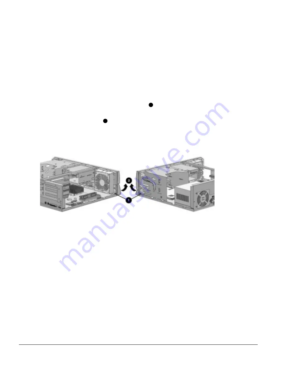
5.1.15.1 Front Bezel
The front bezel is mounted to the computer cover with release latches that are integrated into the bezel.
To remove the front bezel, complete the following steps.
1. Perform the preparation procedures described in Section 5.1.3.
2. Remove the system unit cover as described in Section 5.1.6.
3. From inside the chassis, push the release latches
1
in and push the bottom of the bezel out and away
from the chassis to release the bezel at those points.
4. Slide the desktop bezel up
2
from the bottom of the chassis.
5. Separate the bezel from the chassis.
Figure 5-29.
Removing the Front Bezel
To replace the front bezel, reverse the above steps, taking care to properly position the hinge points
and the release latches before pushing the bezel back into the chassis.
5.1.15.2 Power Button
To remove the power button, complete the following steps:
1. Perform the preparation procedures described in Section 5.1.3.
2. Remove the system unit cover as described in Section 5.1.6.
3. Remove the front bezel as described in Section 5.1.15.1.
4. Hold the front system unit cover in one hand with the inside surface towards you.
Summary of Contents for Deskpro 2000 Series
Page 1: ...MAINTENANCE SERVICE GUIDE COMPAQ DESKPRO 2000 SERIES OF PERSONAL COMPUTERS...
Page 2: ...243064 001 243211 001...
Page 4: ...CPS...
Page 32: ...1 20 Product Description Figure 1 6 Drive Positions on the Minitower Computer...
Page 34: ...1 22 Product Description Figure 1 7 Rear Panel Connectors...
Page 82: ...3 2 Illustrated Parts Catalog 3 1 System Unit Figure 3 2 System Unit Desktop...
Page 84: ...3 4 Illustrated Parts Catalog Figure 3 3 System Unit Minitower...
Page 86: ...3 6 Illustrated Parts Catalog 3 2 Mass Storage Devices Figure 3 4 Mass Storage Devices...
Page 88: ...3 8 Illustrated Parts Catalog 3 3 Cables Figure 3 5 Cables...
Page 96: ...3 16 Illustrated Parts Catalog 3 6 Monitors Figure 3 9 Monitors...


