background image

BBG1070QS-OM (V1.8)

BBG-1070-QS PRODUCT MANUAL

3-45

Setup/Operating Instructions

BBG-1070-QS Function Menu List and Descriptions

(continued)

Table 3-1

BBG-1070-QS Function Menu List — continued

PIP 1 (A1)

PIP 2 (A2)

PIP 3 (A3)

PIP 5 (A5)

PIP 4 (A4)

PIP 6 (B1)

PIP 9 (B4)

PIP 8 (B3)

PIP 7 (B2)

PIP 10 (C1)

PIP 13 (C4)

PIP 12 (C3)

PIP 11 (C2)

PIP 14 (D1)

PIP 17 (D4)

PIP 16 (D3)

PIP 15 (D2)

4

All of the PiP Layout, ARC/Borders, Tally, UMD/Idents, and other graphical attributes are under the cloning “umbrella” 
(i.e., attributes can be set up for a given PiP and then cloned across others as desired). Knowing the desired general 
layout, set up any PiP meeting your layout desires, and then clone and modify the settings to achieve the overall desired 
layout. The example below shows some examples of setting up a given PiP, and then cloning and “tweaking” the settings 
for another PiP.

Note: Refer to setup control sections (e.g., PIP ARC/Borders Controls, UMD/Identification Text Insertion Controls, etc.) 

for specific instructions on using the particular graphic tool.

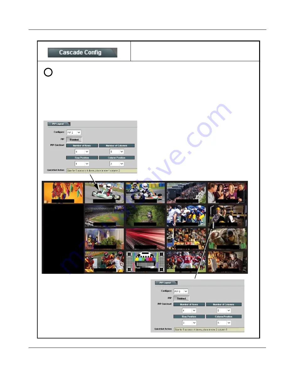
In the example layout shown, knowing a layout with 4 rows and 5 columns is desired, the PiP Layout settings for any PiP can be 
set for 4x5 rows/columns as shown. In this example starting with PiP 2, the row 1 position and column 2 position is set and 
applied, and the PiP is sized accordingly (20x25 in this example).

Once this is done, this PiP is cloned across all PiPs to establish the 
baseline consistency across all PiPs. Then after this, the row/column 
positions for the other PiPs can be tweaked to place them as 
desired. Other attributes such as UMD/Idents and Tallies are then 
group cloned and then tweaked as desired.

Using the global 4x5 rows/columns layout, PiP 2 is accordingly 
sized and set up to be positioned in Row Position 1 and Column 
Position 2. This baseline setting is cloned across all PiPs.

Using the global cloned settings from PiP 2, PiP 9 is set up by 
using all cloned settings and simply tweaking the Row/Column 
positions to place it as desired.

In this example, the UMD/Idents are also cloned, with the only 
tweaks necessary being the ID values.

Note that any PiP settings can be accessed from any unit in the 
cascade chain.

Note: User custom text entered in UMD or Ident cells must be 

manually entered for each UMD and/or Ident cell. User 
custom text cannot be cloned from one PiP to another.

Column 1

5

4

3

2

1R

o

w

43

2

Summary of Contents for BBG-1070-QS

Page 1: ...IL 61821 Voice 217 344 1243 Fax 217 344 1245 www cobaltdigital com Product Manual BBG1070QS OM V1 8 Cobalt Digital Inc 3G HD SD SDI CVBS Standalone Expandable Multiviewer with Advanced On Screen Graph...

Page 2: ...d is a trademark of Ross Video Limited Dolby is a registered trademark of Dolby Laboratories Inc Other product names or trademarks appearing in this manual are the property of their respective owners...

Page 3: ...Setup Overview 1 8 User Control Interface 1 11 Technical Specifications 1 11 Warranty and Service Information 1 13 Cobalt Digital Inc Limited Warranty 1 13 Contact Cobalt Digital Inc 1 14 Chapter 2 In...

Page 4: ...ontrols 3 38 Output Audio Routing Controls 3 40 Cascade Config Setup Controls 3 41 Protocols Router Integration Controls 3 46 GPI Setup Controls 3 48 Event Actions Setup Controls 3 49 Output Preview 3...

Page 5: ...ing personnel who will be using the BBG 1070 QS to manipulate and configure the multi split PiP multiviewer functions day to day use of this product It is recommended that this condensed guide be made...

Page 6: ...s to the HPF 9000 OG3 FR 8321 or similar 20 slot frame that houses Cobalt or other cards Device and or Card refers to a Cobalt or other card System and or Video System refers to the mix of interconnec...

Page 7: ...CE PERSONNEL CAUTION This device is intended for environmentally controlled use only in appropriate video terminal equipment operating environments CAUTION This device contains no user serviceable com...

Page 8: ...ut HDMI DVI OUT Multi image HDMI DVI out with selectable audio embedding suitable for direct connection to monitor panels Video Processing Description The BBG 1070 QS features input select and validit...

Page 9: ...g Alignment 5 1 Video Combiner Formatting Identity Text Burn In Formatting Ident Text User Entry Per PiP ARC Scale Control Audio Alignment Control Frame Ref Select Failover FRAME LOOP Tally Graphics I...

Page 10: ...lor can be user configured Quint Timing Alignment Function This function provides for frame alignment control of the five PiP inputs using either the external FRAME LOOP reference signal or a selected...

Page 11: ...efined actions Tally activation can also be controlled via IP from an automation system router UMD text can be inserted using local user text entry or integrated with router automation to receive text...

Page 12: ...m 2 bar stereo up to all four embedded audio groups for the audio associated with the PiP input User controls allow setting meter complement position size and other graphic attributes Cascading Multi...

Page 13: ...d cascading underlay of preceding device A eight PiPs are now positioned in the two resulting columns B B G 1 0 7 0 Q S D e v i c e B PiP 1 IN PiP 2 IN PiP 3 IN PiP 4 IN PiP 5 IN Cascaded A1 A4 B1 B4...

Page 14: ...P 10 13 Video In PiP 14 17 Video In Cascade Underlay 10 99 11 1 10 99 11 2 10 99 11 4 10 99 11 3 Multi Viewer Video Out DashBoard Remote Control Cascade Config DashBoard tabs and multi unit network co...

Page 15: ...en Power consumption 18 Watts maximum Power provided by included AC adapter 100 240 VAC 50 60 Hz Second DC power connection allows power redundancy using second optional AC adapter Installation Densit...

Page 16: ...minal blocks Phoenix PN 1803581 Cobalt PN 5000 0013 000R Triggering User configurable GPI activation invokes a selected user preset Response GPI acknowledge upon falling edge input triggered by R 10 k...

Page 17: ...tering the product by completing and returning a product registration form In the event of a warrantable defect the purchaser shall notify Cobalt with a description of the problem and Cobalt shall pro...

Page 18: ...gh and professional support representatives for any of the following Name and address of your local dealer Product information and pricing Technical support Upcoming trade show information Phone 217 3...

Page 19: ...ked with stamped x If feet are not affixed chassis bottom cooling vents will be obscured Where BBG 1070 QS is to be installed with optional frame Mounting Tray BBG 1000 TRAY do not affix adhesive back...

Page 20: ...C inputs are internally 75 ohm terminated It is not necessary to terminate unused BNC video inputs or outputs External frame sync reference signal if used must be terminated if a looping daisy chain c...

Page 21: ...QS Dimensional Details 1 73 15 26 1 75 FEET REMOVABLE FEET 4 PLACES 14 30 5 80 1 65 FRONT REAR TOP Notes 1 All dimensions in inches 2 If BBG 1070 QS is mounted on flat surface either rubber feet must...

Page 22: ...vide power redundancy 10 100 1000 ETHERNET Gigabit Ethernet control monitoring connection Communication activity status is shown by integral status LEDs REF LOOP Looping 75 reference connection for co...

Page 23: ...ion Menu List and Descriptions p 3 9 Uploading Firmware Using Web Interface and GUI p 3 60 Front Panel User Menus p 3 61 Troubleshooting p 3 61 Perform the setup procedures here in the sequence specif...

Page 24: ...ss and enter the menu item When this button is pressed the selected menu item is displayed along with its sub menus In this example showing the Network Settings menu Menu Network Settings as menu item...

Page 25: ...Product BBG 1070 is displayed device is ready for configuration 2 Press and access the Network Settings menu Current network settings are displayed as configured by host DHCP server Note It is recomme...

Page 26: ...s within a network also available via DashBoard a BBG 1070 device appears as a frame entity in the DashBoard Basic Tree View Note BBG 1070 DashBoard remote control is also available by opening the dev...

Page 27: ...sist of parameter groups as shown below Figure 3 3 shows how the BBG 1070 QS device and its menus are organized and also provides an overview of how navigation is performed between devices function me...

Page 28: ...ar numeric parametric values can then be adjusted as desired using the GUI slider controls Items in a list can then be selected using GUI drop down lists Figure 3 4 Typical Web UI Display and Controls...

Page 29: ...rface theme selection offers light and dark themes suited for various users and environments Figure 3 5 Web UI Display Themes Clicking Settings opens a pane where the display Theme can be set Light th...

Page 30: ...status display Note Proper operating status is denoted by green icons for the status indicators shown in Figure 3 6 Yellow or red icons respectively indicate an alert or failure condition Refer to Tr...

Page 31: ...e to the page numbers where each function menu item can be found Some functions use sub tabs to help maintain clarity and organization In these instances Table 3 1 shows the ordinate tab along with it...

Page 32: ...e where required Input Routing PiP Input Source Select Routes the SDI inputs VID IN A thru VID IN E as In A thru In E respectively to the respective PiP input In this example VID IN A thru VID IN E ar...

Page 33: ...size with all sizing and positioning controls locked out for this PiP insertion Disabled Sets PiP 5 input to be used as regular input with full aspect and sizing positioning control and burn ins as Pi...

Page 34: ...ould be expected when using this mode Enabled Manual alignment Similar to the Automatic alignment mode this mode will disable low latency framesync bypass when needed However it will not apply alignme...

Page 35: ...nfig mode setup Clone Settings from any of the units in the chain can be cloned to any unit in the chain i e all units in the chain appear in the Clone Settings From and Clone Settings To drop downs S...

Page 36: ...preset global base layout templates from the choices shown and depicted below Note The Preset templates described below are intended for non cascading layouts For symmetrical cascaded layouts layouts...

Page 37: ...ning edits and enables PiP insertion into the merged output In this example PiP 1 is selected for editing Note These controls are intended only for local inputs and not a cascade underlay imported fro...

Page 38: ...1 BBG 1070 QS Function Menu List continued The Number of Rows and Number of Columns drop downs set the grid format to be used for a multi unit multiviewer setup Once the number of rows columns is set...

Page 39: ...Enabled This places the first unit output as an underlay with its merged PiP output positioned in the first column Unit A CAM 1 CAM 4 in 1st column Unit B CAM 1 CAM 4 in 1st column imported as underl...

Page 40: ...llow manipulating PiP position and size as desired Table 3 1 BBG 1070 QS Function Menu List continued PiP 2 with custom positioning sizing placed in normal upper right corner of merged quint split out...

Page 41: ...pear in the Clone Settings From and Clone Settings To drop downs See Cascade Config Setup Controls p 3 41 for more information PiP Border Size Enable Control PIP Border Size sets the border thickness...

Page 42: ...lectors Selects between the standard preset Aspect Ratio Conversions ARC shown below User defined Aspect Ratio Controls Aspect Ratio Horizontal and Aspect Ratio Vertical controls adjust horizontal and...

Page 43: ...nal actions such as GPI see Event Actions Setup Controls p 3 49 for setting up tally lamp control The controls here enable lamp overlay insertion and set size and position attributes These controls do...

Page 44: ...of the positions shown here When Custom is selected tally lamp position and size is configured using the controls described below Note Tally Lamp 1 has anchored position Left of UMD and is intended fo...

Page 45: ...cloned to any unit in the chain i e all units in the chain appear in the Clone Settings From and Clone Settings To drop downs See Cascade Config Setup Controls p 3 41 for more information UMD Insertio...

Page 46: ...field Note The sizing positioning controls below for text and background have an interrelation where a background shading box can automatically track with text size position and vice versa as describe...

Page 47: ...low When Custom is selected the Horizontal and Vertical Position controls allow fine adjustment of the text background positioning Text Box Size selects from Auto in which the box size tracks with the...

Page 48: ...desired ident text string Enter desired text as click Update when done to input the text string Note All normal keyboard alphanumeric characters are supported Not all ASCII special characters Windows...

Page 49: ...Size drop downs set text size in pixels Text Justification selects from left center or right aligned text Character and Background Color drop downs select text and background colors from various inde...

Page 50: ...om is selected the Horizontal and Vertical Position controls allow fine adjustment of the text background positioning Text Box Size selects from Auto in which the box size tracks with the configured t...

Page 51: ...ned to any unit in the chain i e all units in the chain appear in the Clone Settings From and Clone Settings To drop downs See Cascade Config Setup Controls p 3 41 for more information Timecode Insert...

Page 52: ...osition Mode drop down ident text and its background can be positioned using template choices as shown or can use the Custom choices which provide basic positioning which can then be further manipulat...

Page 53: ...for Audio Meter insertion edits as described below Allows cloning settings to other PiPs Note For multi unit setup using Cascade Config mode setup Clone Settings from any of the units in the chain ca...

Page 54: ...Meters control Position controls raise the meter base when the control setting is increased and move the display as a unit left or right Note Where custom channel number complement is configured chann...

Page 55: ...ontrol Sets the relative height of the audio bars Meter Height Control Sets the relative height of the audio bars Meter Opacity Control Sets the relative opacity of the audio bars Table 3 1 BBG 1070 Q...

Page 56: ...dio bar Meter Brightness Control Adjusts relative brightness of audio meter bars display Meter Background Select Provides choice of three background themes for each meter bar Table 3 1 BBG 1070 QS Fun...

Page 57: ...in can be cloned to any unit in the chain i e all units in the chain appear in the Clone Settings From and Clone Settings To drop downs See Cascade Config Setup Controls p 3 41 for more information In...

Page 58: ...e Size control is locked to Custom for this unit with safe action area size control as described above Safe Title Area STA Controls STA provides enable disable of safe title area graticule insertion S...

Page 59: ...th control height of vertical line and width of horizontal line from 0 to 100 of 4 3 outputted image area Horizontal Line Controls Horizontal Line provides enable disable of horizontal line insertion...

Page 60: ...e dropped when performing such conversions Underscan Select Provides underscanning to reduce the merged output raster size by choices shown 16x10 Compensation Select Provides compensating rescaling to...

Page 61: ...is recommended to use Manual mode and force the desired mode as described below HDMI DVI Format Manual Forced Mode Control When set to Manual Control sets HDMI output as forced HDMI or DVI mode HDMI C...

Page 62: ...Controls Allows enable disable of embedded audio groups 1 thru 4 on program video output to accommodate some legacy downstream systems that may not support all four embedded audio groups Note Changin...

Page 63: ...and then save the preset on the last unit in the chain This helps ensure that all saved states in each unit will be saved in an umbrella preset encompassing all units in the chain Table 3 1 BBG 1070...

Page 64: ...d button shows Connected Net Status fields show connection status of each entered unit Self indicates unit that is currently being viewed in setup dialog Connected indicates other unit that is defined...

Page 65: ...om a single point rather than going from unit to unit In our example the PIP Layout drop down now has Configure definers for PiPs 1 thru 17 instead of just PiPs 1 thru 5 for a single non networked uni...

Page 66: ...nits are entered in the A thru D definer slots in Cascade Config page When all unit IP s are entered click Connect The units are now connected in the Cascade mode Q S A Q S B Q S C Q S D PiP 1 5 Video...

Page 67: ...5 columns is desired the PiP Layout settings for any PiP can be set for 4x5 rows columns as shown In this example starting with PiP 2 the row 1 position and column 2 position is set and applied and th...

Page 68: ...for Utah router address Note When router access fetch is enabled UMD text is asserted by Utah router commands The UMD Display Format control is locked to External Input with user text entry or other U...

Page 69: ...tegrating TSL router IP communication with BBG 1070 QS to provide automated UMD and Tally burn ins independently for PiP 1 thru PiP 5 Router Enable Correlate to PiP Controls TSL router messages typica...

Page 70: ...triggers defined as other than Don t Care become true in this case the GPI 1 and GPI 2 2 conditions shown In the GPI Condition 15 example shown here the GPI inputs are not used set to Don t Care whil...

Page 71: ...eived Tally Select allows selecting tally lamp 1 and or 2 attribute actions to be applied when a trigger is true Tally Color assigns a color to be applied to the selected lamp when a trigger is true B...

Page 72: ...as a trigger Event 1 the event action sets the tally lamp 1 to green When GPI Condition 2 is active Event 2 the event action sets the tally lamp 1 to red In this example Video Format is used as a tri...

Page 73: ...hen the Screen Capture button is pressed Capture Automatically provides periodic samplings consisting of a new capture about every 5 seconds It is recommended to set the Screen Capture Mode control to...

Page 74: ...allow transparency or PiP windows such that the graphic does not obscure the PiP image Consult Product Support with any questions or for questions regarding file formats and sizing User Graphic Overl...

Page 75: ...Set Time allows entry of user time and also allows entry of user text identifying the time zone or other text this time zone text is displayed when entered for either user time or NTP time Click Set T...

Page 76: ...s concerned with Limiting presets to a layer or area of concern allows for highly specific presets and masks changing settings in areas outside of the layer or area of concern Default All setting will...

Page 77: ...he chain This helps ensure that all saved states in each unit will be saved in an umbrella preset encompassing all units in the chain Table 3 1 BBG 1070 QS Function Menu List continued Protected state...

Page 78: ...sets that may not apply to other units in the chain need to updated as described here For subsequent presets remove all IPs from the Cascade Config tab and click Disconnect Then load the presets and t...

Page 79: ...t the bottom of DashBoard 2 Browse to the location of the firmware upgrade file in this example My Documents v1 0 0019 bin 3 Select the desired file and click Open to upload the file to the unit Immed...

Page 80: ...should be avoided under normal conditions to ensure maximum protection Card Network Setup Controls Note The IP address setting here is independent of a frame IP typically used for DashBoard or other...

Page 81: ...dress where NTP is to be obtained Local Timezone sets the recorded time to the localized time NTP Status shows if time is synced with NTP or if an error exists User Log Automatically maintains a log o...

Page 82: ...ctly via the web html5 interface without going through DashBoard see Figure 3 7 In addition to allowing uploads without needing a DashBoard connection this method transfers files typically much faster...

Page 83: ...asic cases Troubleshooting This section provides general troubleshooting information and specific symptom corrective action for the BBG 1070 QS and its remote control interface The BBG 1070 QS require...

Page 84: ...nction Alphanumeric Display Shows device statuses STATUS LED Illuminates GREEN indicating BBG 1070 QS has successfully powered up and passed self tests INPUT LOCK LED Illuminates GREEN indicating sign...

Page 85: ...presence and characteristics On the BBG 1070 QS in all cases when power is being properly supplied all indicators should be illuminated Any device showing no illuminated indicators should be cause fo...

Page 86: ...QS device See Input Routing p 3 10 controls for more information Cannot set UMD text Display Format to choice other than External Input Protocols tab inadvertently set to use router for UMD assert bu...

Page 87: ...recommended to set the Screen Capture Mode control to Capture On Trigger or entirely disable Output Preview when the preview function is no longer needed When the mode is set to capture on trigger or...

Page 88: ...off on and then off again entire process takes about 1 1 2 minute 4 Remove power from the card remove card from slot or power down BBG 1000 Series unit 1 From underside of card locate the SD card rec...

Page 89: ...t that was not solved by the information in this section please contact the Cobalt Digital Inc Technical Support Department If required a Return Material Authorization number RMA will be issued to you...

Page 90: ...3 68 BBG 1070 QS PRODUCT MANUAL BBG1070QS OM V1 8 This page intentionally blank...

Page 91: ......

Page 92: ...Cobalt Digital Inc 2506 Galen Drive Champaign IL 61821 Voice 217 344 1243 Fax 217 344 1245 www cobaltdigital com BBG1070QS OM V1 8 Printed in USA...

Reviews: