3
BBG-1070-QS Function Menu List and Descriptions
3-42
BBG-1070-QS PRODUCT MANUAL
BBG1070QS-OM (V1.8)
(continued)
Cascade Configurator Network Setup
Table 3-1
BBG-1070-QS Function Menu List — continued
Cascade Configurator Network Setup
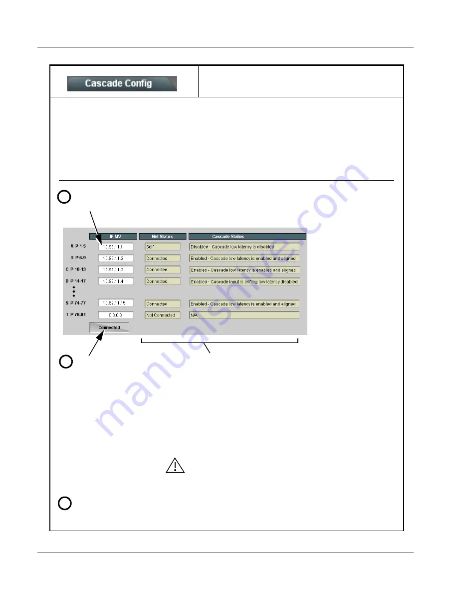
The configurator definer tool defines the BBG-1070-QS units within a particular cascade chain by unit IP address, and each unit’s
position within the multiviewer setup. The setup is based on BBG-1070-QS units being used with the first unit receiving 5 program
video inputs, and subsequent cascade BBG-1070-QS units each receiving an upstream cascade underlay (on PiP 5 In) with 4
program video inputs being received on PiP In 1 thru PiP In 4 (in other words, as a 5 + 4n matrix, with n being the number of
downstream cascade units).
This allows multiviewer setups using up to 20 units (A thru T in the definer shown below) to provide an up to 81-split combined
multiviewer image.
1
Assign each unit in the cascade chain a dedicated IP address (if not done so already). Working from the starting unit to
each downstream cascade unit, enter the unit IP address in each IP MV field.
2
When done, click the Connect
button. When all units enter are
connected, button shows
Connected.
Net Status fields show connection status of each entered unit.
• Self indicates unit that is currently being viewed in setup dialog.
• Connected indicates other unit that is defined in dialog .
• Not Connected indicates that unit IP hasn’t been entered in IP MV row, or
simply a blank MV definer row that isn’t being used.
• Connection Failed indicates a unit that has IP entered is no longer
connected (due to cabling issue or other network issue).
Cascade Status fields show cascade mode settings (Enabled or Dsiabled)
and status for each defined unit in the chain (as shown in the example here,
first unit in chain is not set for cascade since it uses all inputs as program video
PiPs).
Note: When all units are connected, this pane is available in all defined units
in the chain.
All BBG-1070-QS units (except for unit in first-unit row A position) must be set
for Cascade Mode. This allows subsequent units to receive the PiP images
from preceding units.
See Cascade Mode Select (p. 3-11) for details on using the cascade mode.
Set up PiP positioning, sizing, and attributes (UMD, Idents, tallies, audio bars etc.) as described in respective sections of
this chapter. Once the definer described above is connected, these attributes for all units can be configured from any unit
in the chain. See the example on the next page for an overview and tips on using Cascade Config.
3


