25
©
2017
Columbus McKinnon Industrial Products GmbH
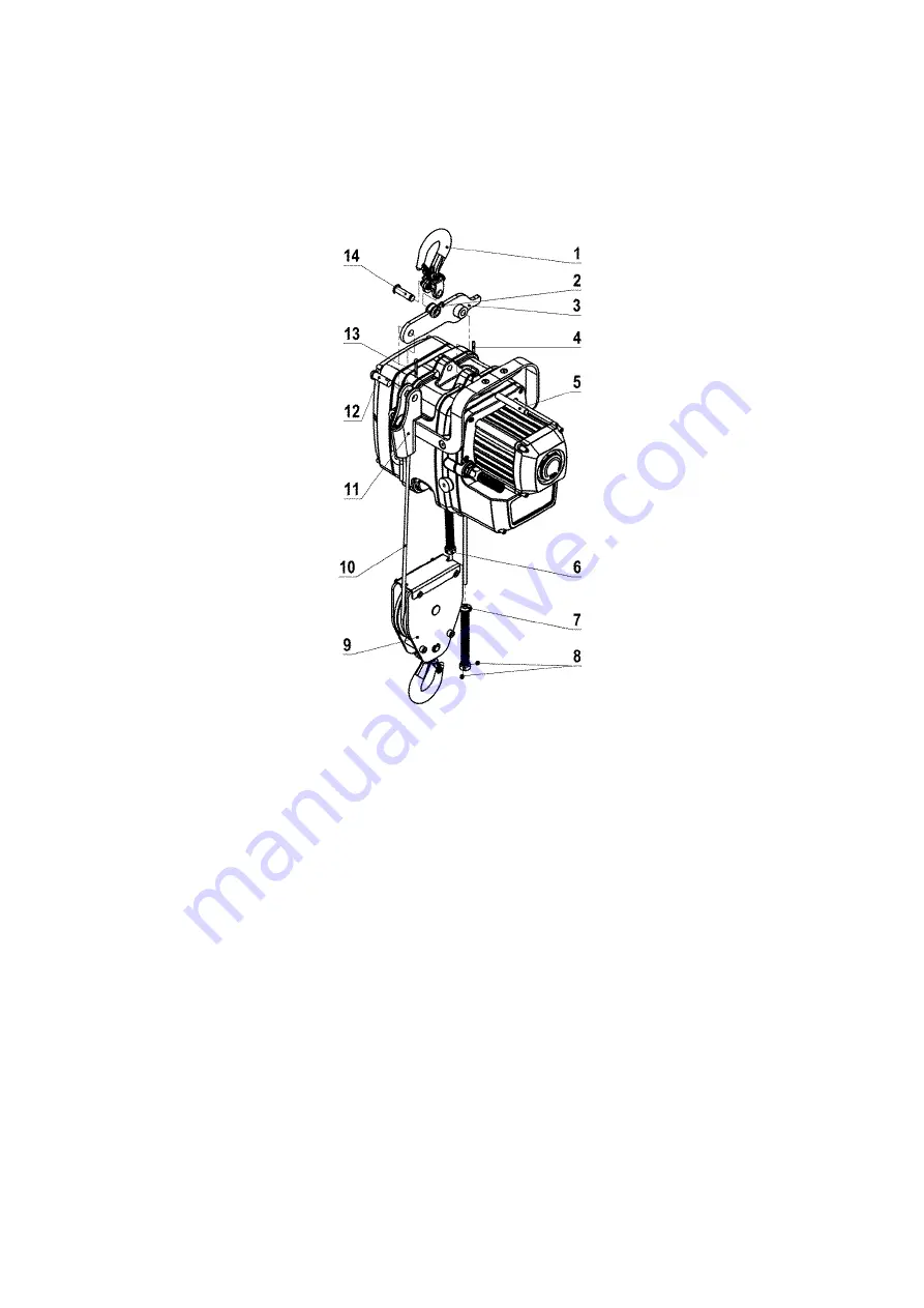
Modification of 1-strand to 2-strand version (optional)
Install support hook (1) and suspension bar (3) with suspension bolt (14) and retaining ring (2).
Then install suspension bar on the main unit with suspension bolts (5) and roll pin (4). Slide support rope with the tip of the cable
through the spring-kit (6) and then through the guide pulley (9). Then mount the wedge end clamp (11) onto the end of the cable as
described. Secure wedge end clamp (11) with pin (12) and split pin (13) on the suspension bar (3). The threaded pins of the shock-
absorbing spring-kit (6) are not tightened or installed here.
The shock-absorbing spring-kit (7) is installed as normal on the other end of the support rope with the threaded pins.
Assembling the second hooks for the pendulum stroke (optional)
As an option, a hook for the pendulum stroke can be mounted on the loose rope end with the aid of a wedge socket.
To do this, after the assembly of the wedge socket the eyelet hook (6) is attached to the wedge socket with the pin (5) and split pin (4).
Installation of a wedge socket (optional)
• Before assembling, check the parts for any signs of damage
• Only use wedge sockets with the appropriate dimensions and break load for the rope used.
• Components of different wedge sockets must not be used together
• If the wedge socket is shifted on the rope, the section of the rope that the clamp was in use on must no longer be in the load line and
must be separated, if necessary
• To install the rope and the wedge in the housing of the wedge socket, both rope ends must be under tension. The wedge should then
be driven in with a tool which does not damage the rope, the wedge and the housing.
Then the system must be loaded under supervision with a load of at least 10 % of the breaking load of the rope, so that the wedge and
rope settle in. The wedge must be seated accurately before the system is put into operation.
• The dead rope end must be secured so that the rope is prevented from pulling through during the creation of the rope connection and
the wedge cannot come loose during operation.
The following methods are recommended:
(a) The dead rope can be bent back to form a loop and secured by means of a wire rope clamp that has a U-shaped clamping bracket
according to EN 13411-5. The loop should be tightly bound to the load-bearing part of the rope with appropriate means such as soft
binding wire, to prevent the rope from protruding during operation.
(b) If there is the possibility that the loop in method a) bumps against an obstacle (for instance, a component in the operation), which
could loosen the wedge and make the rope pull through, the dead rope end should not be bent back, but placed parallel to the load-
bearing part of the rope. A spacer or a short rope end with the same diameter and a rope cable clamp with U-shaped clamp according
to EN 13411-5 are required to ensure that the rope is secured sufficiently. If necessary, the dead rope end can be bound tightly with soft
binding wire to the load-bearing section.
Summary of Contents for YaleMtrac Mini YMT1-15
Page 16: ...16 2017 Columbus McKinnon Industrial Products GmbH...
Page 32: ...32 2017 Columbus McKinnon Industrial Products GmbH...
Page 48: ...48 2017 Columbus McKinnon Industrial Products GmbH...
Page 64: ...64 2017 Columbus McKinnon Industrial Products GmbH...
Page 80: ...80 2017 Columbus McKinnon Industrial Products GmbH...
Page 96: ...96 2017 Columbus McKinnon Industrial Products GmbH...
Page 112: ...112 2017 Columbus McKinnon Industrial Products GmbH...
Page 128: ...128 2017 Columbus McKinnon Industrial Products GmbH...
Page 144: ...144 2017 Columbus McKinnon Industrial Products GmbH...
Page 160: ...160 2017 Columbus McKinnon Industrial Products GmbH...
Page 176: ...176 2017 Columbus McKinnon Industrial Products GmbH...
Page 180: ...180 2017 Columbus McKinnon Industrial Products GmbH Yale Yale 2 40 C 70 C...
Page 181: ...181 2017 Columbus McKinnon Industrial Products GmbH 3...
Page 184: ...184 2017 Columbus McKinnon Industrial Products GmbH MoS2 2x 2 5 1 4 3 CEE 3 1 2 3 5 SW 3 3...
Page 186: ...186 2017 Columbus McKinnon Industrial Products GmbH X 75 X X 1 CMCO...
Page 187: ...187 2017 Columbus McKinnon Industrial Products GmbH...
Page 188: ...188 2017 Columbus McKinnon Industrial Products GmbH Yale 12 1 5 1 2...
Page 191: ...191 2017 Columbus McKinnon Industrial Products GmbH www cmco eu...
Page 192: ...192 2017 Columbus McKinnon Industrial Products GmbH...


