EQ 1000
MOTORIZED WHEEL BALANCER WITH DIGITAL DISPLAY
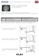
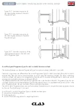
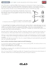
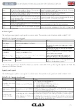
3. Bring the valve to the 12 o’clock position, mark the valve position on the tyre (see fi gure F5.4)
Fig. F5.4 - Marking of the valve position on the tyre 4. Press [P4]. The
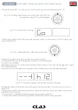
message seen in fi gure F5.5 will be displayed
Fig. F5.5 “Run the launch” message
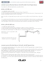
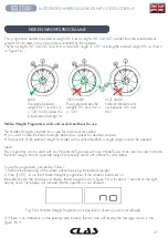
5. Remove the wheel from the shaft, remove the tyre bead, rotate it so that the mark is at 180° respect to the
valve (see fi gure F5.6)
Fig. F5.6 - Marking the tyre at 180° respect to the valve
6. Remount the wheel on the shaft, erase the mark and run a launch;
7. At the end of the cycle, the message seen in fi gure F5.3 will be displayed.
Two options are available:
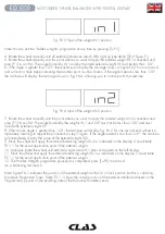
a) Bring the valve to the 12 o’clock position and press [P4] to continue. In this case, the message seen in fi gure
F5.7 will be displayed.
b) Press [F+P4] to exit the optimisation programme and to directly return to the operating programme;
Fig. F5.7 “Final valve alignment with the mark on the tyre” message
8. Rotate the wheel until all position arrow LEDs light up and then mark the 12 o’clock position as shown in
fi gure F5.4;
9. Remove the wheel from the balancing machine, remove the bead from the tyre and rotate it until the valve
matches the mark on the tyre;
10. Optimisation is completed: exit the optimisation menu by pressing [F+P4].
11. Remount the wheel on the balancing machine and balance it with the normal procedure.
Summary of Contents for EQ 1000
Page 29: ...29 EQ 1000 EQUILIBREUSE ROUES MOTORISEE AFFICHAGE DIGITAL ...
Page 75: ...NOTES ...

